DataLink Layer
DataLink Layer - Accessing the Media
Data Link Layer - Supporting & Connecting to Upper Layer Services
The Data Link layer provides a means for exchanging data over a common local media.
The Data Link layer performs two basic services:
-
Allows the upper layers to access the media using techniques such as framing
- Controls how data is placed onto the media and is received from the media using techniques such as media access control and error detection
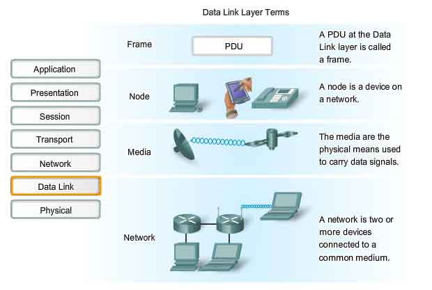
As with each of the OSI layers, there are terms specific to this layer:
Frame - The Data Link layer PDU
Node - The Layer 2 notation for network devices connected to a common medium
Media/medium (physical)* - The physical means for the transfer of information between two nodes
Network (physical)** - Two or more nodes connected to a common medium
The Data Link layer is responsible for the exchange of frames between nodes over the media of a physical network.
* It is important to understand the meaning of the words medium and media within the context of this chapter. Here, these words refer to the material that actually carries the signals representing the transmitted data. Media is the physical copper cable, optical fiber, or atmosphere through which the signals travel. In this chapter media does not refer to content programming such as audio, animation, television, and video as used when referring to digital content and multimedia.
** A physical network is different from a logical network. Logical networks are defined at the Network layer by the arrangement of the hierarchical addressing scheme. Physical networks represent the interconnection of devices on a common media. Sometimes, a physical network is also referred to as a network segment.
Upper Layer Access to Media
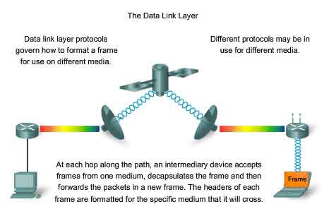
As we have discussed, a network model allows each layer to function with minimal concern for the roles of the other layers. The Data Link layer relieves the upper layers from the responsibility of putting data on the network and receiving data from the network. This layer provides services to support the communication processes for each medium over which data is to be transmitted. In any given exchange of Network layer packets, there may be numerous Data Link layer and media transitions. At each hop along the path, an intermediary device - usually a router - accepts frames from a medium, decapsulates the frame, and then forwards the packet in a new frame appropriate to the medium of that segment of the physical network. Imagine a data conversation between two distant hosts, such as a PC in Paris with an Internet server in Japan. Although the two hosts may be communicating with their peer Network layer protocols (IP for example), it is likely that numerous Data Link layer protocols are being used to transport the IP packets over various types of LANs and WANs. This packet exchange between two hosts requires a diversity of protocols that must exist at the Data Link layer. Each transition at a router could require a different Data Link layer protocol for transport on a new medium. Notice in the figure that each link between devices uses a different medium. Between the PC and the router may be an Ethernet link. The routers are connected through a satellite link, and the laptop is connected through a wireless link to the last router. In this example, as an IP packet travels from the PC to the laptop, it will be encapsulated into Ethernet frame, decapsulated, processed, and then encapsulated into a new data link frame to cross the satellite link. For the final link, the packet will use a wireless data link frame from the router to the laptop. The Data Link layer effectively insulates the communication processes at the higher layers from the media transitions that may occur end-to-end. A packet is received from and directed to an upper layer protocol, in this case IPv4 or IPv6, that does not need to be aware of which media the communication will use. Without the Data Link layer, a Network layer protocol, such as IP, would have to make provisions for connecting to every type of media that could exist along a delivery path. Moreover, IP would have to adapt every time a new network technology or medium was developed. This process would hamper protocol and network media innovation and development. This is a key reason for using a layered approach to networking. The range of Data Link layer services has to include all of the currently used types of media and the methods for accessing them. Because of the number of communication services provided by the Data Link layer, it is difficult to generalize their role and provide examples of a generic set of services. For that reason, please note that any given protocol may or may not support all these Data Link layer services.
ISO 7498 :
http://www.sigcomm.org/standards/iso_stds/OSI_MODEL/ISO_IEC_7498-1.TXT
Internetworking Basics :
http://www.cisco.com/univercd/cc/td/doc/cisintwk/ito_doc/introint.htm#wp1020777
MTU :
http://www.tcpipguide.com/free/t_IPDatagramSizeMaximumTransmissionUnitMTUFragmentat.htm
Data Link Layer - Controlling Transfer across Local Media
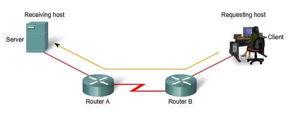
Layer 2 protocols specify the encapsulation of a packet into a frame and the techniques for getting the encapsulated packet on and off each medium. The technique used for getting the frame on and off media is called the media access control method. For the data to be transferred across a number of different media, different media access control methods may be required during the course of a single communication. Each network environment that packets encounter as they travel from a local host to a remote host can have different characteristics. For example, one network environment may consist of many hosts contending to access the network medium on an ad hoc basis. Another environment may consist of a direct connection between only two devices over which data flows sequentially as bits in an orderly way. The media access control methods described by the Data Link layer protocols define the processes by which network devices can access the network media and transmit frames in diverse network environments. A node that is an end device uses an adapter to make the connection to the network. For example, to connect to a LAN, the device would use the appropriate Network Interface Card (NIC) to connect to the LAN media. The adapter manages the framing and media access control. At intermediary devices such as a router, where the media type could change for each connected network, different physical interfaces on the router are used to encapsulate the packet into the appropriate frame, and a suitable media access control method is used to access each link. The router in the figure has an Ethernet interface to connect to the LAN and a serial interface to connect to the WAN. As the router processes frames, it will use Data Link layer services to receive the frame from one medium, decapsulate it to the Layer 3 PDU, re-encapsulate the PDU into a new frame, and place the frame on the medium of the next link of the network.
Data Link Layer - Creating a Frame
The description of a frame is a key element of each Data Link layer protocol. Data Link layer protocols require control information to enable the protocols to function. Control information may tell:
-
Which nodes are in communication with each other
- When communication between individual nodes begins and when it ends
- Which errors occurred while the nodes communicated
- Which nodes will communicate next
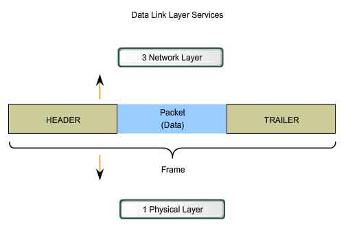
The Data Link layer prepares a packet for transport across the local media by encapsulating it with a header and a trailer to create a frame. Unlike the other PDUs that have been discussed in this course, the Data Link layer frame includes:
-
Data - The packet from the Network layer
- Header - Contains control information, such as addressing, and is located at the beginning of the PDU
- Trailer - Contains control information added to the end of the PDU
Formatting Data for Transmission
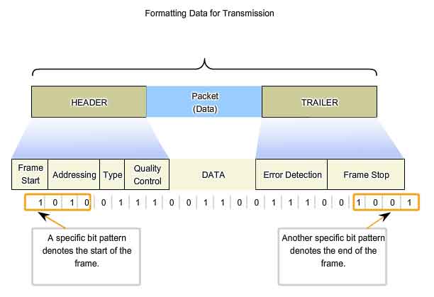
When data travels on the media, it is converted into a stream of bits, or 1s and 0s. If a node is receiving long streams of bits, how does it determine where a frame starts and stops or which bits represent the address?
Framing breaks the stream into decipherable groupings, with control information inserted in the header and trailer as values in different fields. This format gives the physical signals a structure that can be received by nodes and decoded into packets at the destination.
Typical field types include:
-
Start and stop indicator fields - The beginning and end limits of the frame
- Naming or addressing fields
- Type field - The type of PDU contained in the frame
- Quality - control fields
- A data field -The frame payload (Network layer packet)
Fields at the end of the frame form the trailer. These fields are used for error detection and mark the end of the frame. Not all protocols include all of these fields. The standards for a specific Data Link protocol define the actual frame format. Examples of frame formats will be discussed at the end of this chapter.
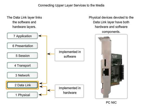
Data Link Layer - Connecting Upper Layer Services to the Media
The Data Link layer exists as a connecting layer between the software processes of the layers above it and the Physical layer below it. As such, it prepares the Network layer packets for transmission across some form of media, be it copper, fiber, or the atmosphere. In many cases, the Data Link layer is embodied as a physical entity, such as an Ethernet network interface card (NIC), which inserts into the system bus of a computer and makes the connection between running software processes on the computer and physical media. The NIC is not solely a physical entity, however. Software associated with the NIC enables the NIC to perform its intermediary functions of preparing data for transmission and encoding the data as signals to be sent on the associated media.
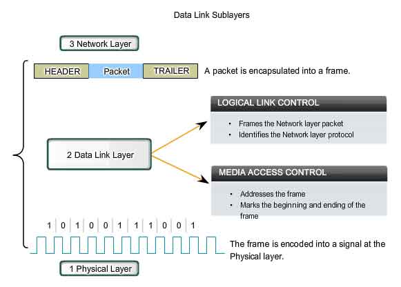
Data Link Sublayers
To support a wide variety of network functions, the Data Link layer is often divided into two sublayers: an upper sublayer and an lower sublayer.
-
The upper sublayer defines the software processes that provide services to the Network layer protocols.
- The lower sublayer defines the media access processes performed by the hardware.
Separating the Data Link layer into sublayers allows for one type of frame defined by the upper layer to access different types of media defined by the lower layer. Such is the case in many LAN technologies, including Ethernet.
The two common LAN sublayers are:
Logical Link Control
Logical Link Control (LLC) places information in the frame that identifies which Network layer protocol is being used for the frame. This information allows multiple Layer 3 protocols, such as IP and IPX, to utilize the same network interface and media.
Media Access Control
Media Access Control (MAC) provides Data Link layer addressing and delimiting of data according to the physical signaling requirements of the medium and the type of Data Link layer protocol in use.
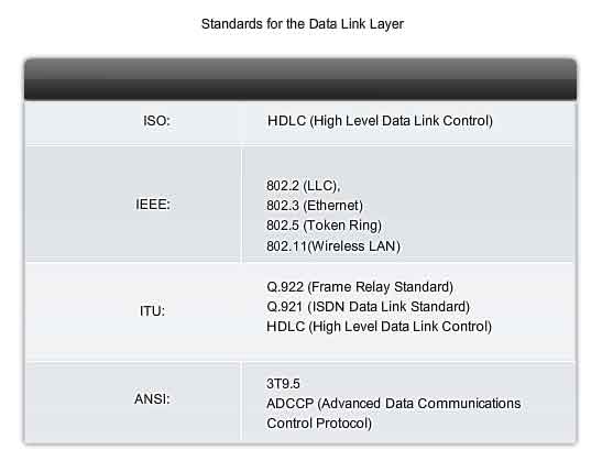
Data Link Layer - Standards
Unlike the protocols of the upper layers of the TCP/IP suite, Data Link layer protocols are generally not defined by Request for Comments (RFCs). Although the Internet Engineering Task Force (IETF) maintains the functional protocols and services for the TCP/IP protocol suite in the upper layers, the IETF does not define the functions and operation of that model's Network access layer. The TCP/IP Network Access layer is the equivalent of the OSI Data Link and Physical layers. These two layer will be discussed in separate chapters for closer examination. The functional protocols and services at the Data Link layer are described by engineering organizations (such as IEEE, ANSI, and ITU) and communications companies. Engineering organizations set public and open standards and protocols. Communications companies may set and use proprietary protocols to take advantage of new advances in technology or market opportunities. Data Link layer services and specifications are defined by multiple standards based on a variety of technologies and media to which the protocols are applied. Some of these standards integrate both Layer 2 and Layer 1 services. Engineering organizations that define open standards and protocols that apply to the Data Link layer include:
-
International Organization for Standardization (ISO)
- Institute of Electrical and Electronics Engineers (IEEE)
- American National Standards Institute (ANSI)
- International Telecommunication Union (ITU)
Unlike the upper layer protocols, which are implemented mostly in software such as the host operating system or specific applications, Data Link layer processes occur both in software and hardware. The protocols at this layer are implemented within the electronics of the network adapters with which the device connects to the physical network. For example, a device implementing the Data Link layer on a computer would be the network interface card (NIC). For a laptop, a wireless PCMCIA adapter is commonly used. Each of these adapters is the hardware that complies with the Layer 2 standards and protocols.
Media Access Control Techniques
Placing Data on the Media
Regulating the placement of data frames onto the media is known as media access control. Among the different implementations of the Data Link layer protocols, there are different methods of controlling access to the media. These media access control techniques define if and how the nodes share the media. Media access control is the equivalent of traffic rules that regulate the entrance of motor vehicles onto a roadway. The absence of any media access control would be the equivalent of vehicles ignoring all other traffic and entering the road without regard to the other vehicles. However, not all roads and entrances are the same. Traffic can enter the road by merging, by waiting for its turn at a stop sign, or by obeying signal lights. A driver follows a different set of rules for each type of entrance. In the same way, there are different ways to regulate the placing of frames onto the media. The protocols at the Data Link layer define the rules for access to different media. Some media access control methods use highly-controlled processes to ensure that frames are safely placed on the media. These methods are defined by sophisticated protocols, which require mechanisms that introduce overhead onto the network.
The method of media access control used depends on:
-
Media sharing - If and how the nodes share the media
- Topology - How the connection between the nodes appears to the Data Link layer
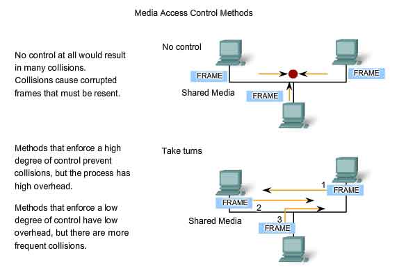
Media Access Control for Shared Media
Some network topologies share a common medium with multiple nodes. At any one time, there may be a number of devices attempting to send and receive data using the network media. There are rules that govern how these devices share the media.
There are two basic media access control methods for shared media:
-
Controlled - Each node has its own time to use the medium
- Contention-based - All nodes compete for the use of the medium
Controlled Access for Shared Media
When using the controlled access method, network devices take turns, in sequence, to access the medium. This method is also known as scheduled access or deterministic. If a device does not need to access the medium, the opportunity to use the medium passes to the next device in line. When one device places a frame on the media, no other device can do so until the frame has arrived at the destination and has been processed by the destination.
Although controlled access is well-ordered and provides predictable throughput, deterministic methods can be inefficient because a device has to wait for its turn before it can use the medium.
Contention-based Access for Shared Media
Also referred to as non-deterministic, contention-based methods allow any device to try to access the medium whenever it has data to send. To prevent complete chaos on the media, these methods use a Carrier Sense Multiple Access (CSMA) process to first detect if the media is carrying a signal. If a carrier signal on the media from another node is detected, it means that another device is transmitting. When the device attempting to transmit sees that the media is busy, it will wait and try again after a short time period. If no carrier signal is detected, the device transmits its data. Ethernet and wireless networks use contention-based media access control. It is possible that the CSMA process will fail and two devices will transmit at the same time. This is called a data collision. If this occurs, the data sent by both devices will be corrupted and will need to be resent. Contention-based media access control methods do not have the overhead of controlled access methods. A mechanism for tracking whose turn it is to access the media is not required. However, the contention-based systems do not scale well under heavy media use. As use and the number of nodes increases, the probability of successful media access without a collision decreases. Additionally, The recovery mechanisms required to correct errors due to these collisions further diminishes the throughput.
CSMA is usually implemented in conjunction with a method for resolving the media contention. The two commonly used methods are:
CSMA/Collision Detection
In CSMA/Collision Detection (CSMA/CD), the device monitors the media for the presence of a data signal. If a data signal is absent, indicating that the media is free, the device transmits the data. If signals are then detected that show another device was transmitting at the same time, all devices stop sending and try again later. Traditional forms of Ethernet use this method.
CSMA/Collision Avoidance
In CSMA/Collision Avoidance (CSMA/CA), the device examines the media for the presence of a data signal. If the media is free, the device sends a notification across the media of its intent to use it. The device then sends the data. This method is used by 802.11 wireless networking technologies.
Media Access Control for Non-Shared Media
Media access control protocols for non-shared media require little or no control before placing frames onto the media. These protocols have simpler rules and procedures for media access control. Such is the case for point-to-point topologies. In point-to-point topologies, the media interconnects just two nodes. In this arrangement, the nodes do not have to share the media with other hosts or determine if a frame is destined for that node. Therefore, Data Link layer protocols have little to do for controlling non-shared media access.
Full Duplex and Half Duplex
In point-to-point connections, the Data Link layer has to consider whether the communication is half-duplex or full-duplex.
See the figure to see the differences in the two methods. Half-duplex communication means that the devices can both transmit and receive on the media but cannot do so simultaneously. Ethernet has established arbitration rules for resolving conflicts arising from instances when more than one station attempts to transmit at the same time. In full-duplex communication, both devices can transmit and receive on the media at the same time. The Data Link layer assumes that the media is available for transmission for both nodes at any time. Therefore, there is no media arbitration necessary in the Data Link layer. The details of a specific media access control technique can only be examined by studying a specific protocol. Within this course, we will study traditional Ethernet, which uses CSMA/CD. Other techniques will be covered in later courses.
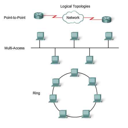
Logical Topology vs Physical Topology
The topology of a network is the arrangement or relationship of the network devices and the interconnections between them. Network topologies can be viewed at the physical level and the logical level.
The physical topology is an arrangement of the nodes and the physical connections between them. The representation of how the media is used to interconnect the devices is the physical topology. These will be covered in later chapters of this course.
A logical topology is the way a network transfers frames from one node to the next. This arrangement consists of virtual connections between the nodes of a network independent of their physical layout. These logical signal paths are defined by Data Link layer protocols. The Data Link layer "sees" the logical topology of a network when controlling data access to the media. It is the logical topology that influences the type of network framing and media access control used.
The physical or cabled topology of a network will most likely not be the same as the logical topology.
Logical topology of a network is closely related to the mechanism used to manage network access. Access methods provide the procedures to manage network access so that all stations have access. When several entities share the same media, some mechanism must be in place to control access. Access methods are applied to networks to regulate this media access. Access methods will be discussed in more detail later. Logical and physical topologies typically used in networks are:
-
Point-to-Point
- Multi-Access
- Ring
The logical implementations of these topologies and their associated media access control methods are considered in the following sections.
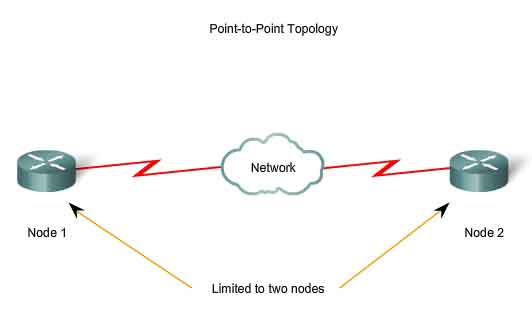
Point-to-Point Topology
A point-to-point topology connects two nodes directly together, as shown in the figure. In data networks with point-to-point topologies, the media access control protocol can be very simple. All frames on the media can only travel to or from the two nodes. The frames are placed on the media by the node at one end and taken off the media by the node at the other end of the point-to-point circuit.
In point-to-point networks, if data can only flow in one direction at a time, it is operating as a half-duplex link. If data can successfully flow across the link from each node simultaneously, it is a full-duplex link.
Data Link layer protocols could provide more sophisticated media access control processes for logical point-to-point topologies, but this would only add unnecessary protocol overhead.
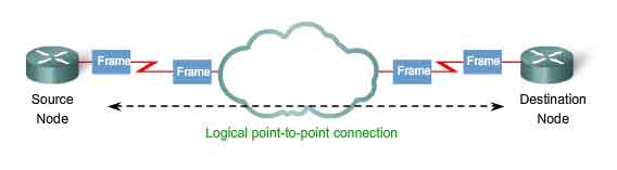
Logical Point-to-Point Networks
The end nodes communicating in a point-to-point network can be physically connected via a number of intermediate devices. However the use of physical devices in the network does not affect the logical topology. As shown in the figure, the source and destination node may be indirectly connected to each other over some geographical distance. In some cases, the logical connection between nodes forms what is called a virtual circuit. A virtual circuit is a logical connection created within a network between two network devices. The two nodes on either end of the virtual circuit exchange the frames with each other. This occurs even if the frames are directed through intermediary devices. Virtual circuits are important logical communication constructs used by some Layer 2 technologies. The media access method used by the Data Link protocol is determined by the logical point-to-point topology, not the physical topology. This means that the logical point-to-point connection between two nodes may not necessarily be between two physical nodes at each end of a single physical link.
Multi-Access Topology
A logical multi-access topology enables a number of nodes to communicate by using the same shared media. Data from only one node can be placed on the medium at any one time. Every node sees all the frames that are on the medium, but only the node to which the frame is addressed processes the contents of the frame. Having many nodes share access to the medium requires a Data Link media access control method to regulate the transmission of data and thereby reduce collisions between different signals. The media access control methods used by logical multi-access topologies are typically CSMA/CD or CSMA/CA. However, token passing methods can also be used. A number of media access control techniques are available for this type of logical topology. The Data Link layer protocol specifies the media access control method that will provide the appropriate balance between frame control, frame protection, and network overhead.
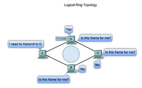
Ring Topology
In a logical ring topology, each node in turn receives a frame. If the frame is not addressed to the node, the node passes the frame to the next node. This allows a ring to use a controlled media access control technique called token passing. Nodes in a logical ring topology remove the frame from the ring, examine the address, and send it on if it is not addressed for that node. In a ring, all nodes around the ring- between the source and destination node examine the frame. There are multiple media access control techniques that could be used with a logical ring, depending on the level of control required. For example, only one frame at a time is usually carried by the media. If there is no data being transmitted, a signal (known as a token) may be placed on the media and a node can only place a data frame on the media when it has the token. Remember that the Data Link layer "sees" a logical ring topology. The actual physical cabling topology could be another topology.
Media Access Control Addressing and Framing Data
Data Link Layer Protocols - The Frame
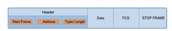
Remember that although there are many different Data Link layer protocols that describe Data Link layer frames, each frame type has three basic parts:
-
Header
- Data
- Trailer
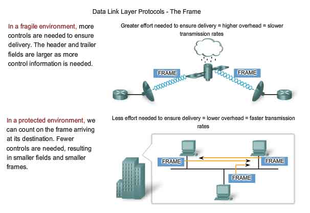
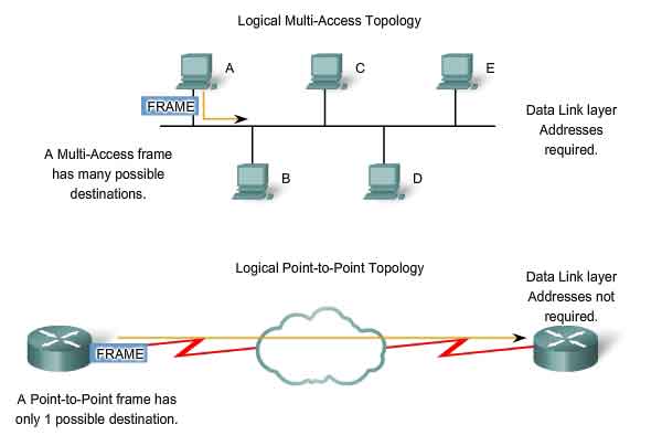
All Data Link layer protocols encapsulate the Layer 3 PDU within the data field of the frame. However, the structure of the frame and the fields contained in the header and trailer vary according to the protocol. The Data Link layer protocol describes the features required for the transport of packets across different media. These features of the protocol are integrated into the encapsulation of the frame. When the frame arrives at its destination and the Data Link protocol takes the frame off the media, the framing information is read and discarded. There is no one frame structure that meets the needs of all data transportation across all types of media. As shown in the figure, depending on the environment, the amount of control information needed in the frame varies to match the media access control requirements of the media and logical topology.
Framing - Role of the Header
The frame header contains the control information specified by the Data Link layer protocol for the specific logical topology and media used. Frame control information is unique to each type of protocol. It is used by the Layer 2 protocol to provide features demanded by the communication environment.
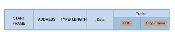
Typical frame header fields include:
-
Start Frame field - Indicates the beginning of the frame
- Source and Destination address fields - Indicates the source and destination nodes on the media
- Priority/Quality of Service field - Indicates a particular type of communication service for processing
- Type field - Indicates the upper layer service contained in the frame
- Logical connection control field - Used to establish a logical connection between nodes
- Physical link control field - Used to establish the media link
- Flow control field - Used to start and stop traffic over the media
- Congestion control field - Indicates congestion in the media
The field names above are nonspecific fields listed as examples. Different Data Link layer protocols may use different fields from those mentioned. Because the purposes and functions of Data Link layer protocols are related to the specific topologies and media, each protocol has to be examined to gain a detailed understanding of its frame structure. As protocols are discussed in this course, more information about the frame structure will be explained.
Addressing - Where the Frame Goes
The data Link layer provides addressing that is used in transporting the frame across the shared local media. Device addresses at this layer are referred to as physical addresses. Data Link layer addressing is contained within the frame header and specifies the frame destination node on the local network. The frame header may also contain the source address of the frame. Unlike Layer 3 logical addresses that are hierarchical, physical addresses do not indicate on what network the device is located. If the device is moved to another network or subnet, it will still function with the same Layer 2 physical address. Because the frame is only used to transport data between nodes across the local media, the Data Link layer address is only used for local delivery. Addresses at this layer have no meaning beyond the local network. Compare this to Layer 3, where addresses in the packet header are carried from source host to destination host regardless of the number of network hops along the route. If the packet in the frame must pass onto another network segment, the intermediate device - a router - will decapsulate the original frame, create a new frame for the packet, and send it onto the new segment. The new frame will use source and destination addressing as necessary to transport the packet across the new media.
Addressing Requirements
The need for Data Link layer addressing at this layer depends on the logical topology. Point-to-point topologies, with just two interconnected nodes, do not require addressing. Once on the medium, the frame has only one place it can go. Because ring and multi-access topologies can connect many nodes on a common medium, addressing is required for these typologies. When a frame reaches each node in the topology, the node examines the destination address in the header to determine if it is the destination of the frame.
Framing - Role of the Trailer
Data Link layer protocols add a trailer to the end of each frame. The trailer is used to determine if the frame arrived without error. This process is called error detection. Note that this is different from error correction. Error detection is accomplished by placing a logical or mathematical summary of the bits that comprise the frame in the trailer.
Frame Check Sequence
The Frame Check Sequence (FCS) field is used to determine if errors occurred in the transmission and reception of the frame. Error detection is added at the Data Link layer because this is where data is transferred across the media. The media is a potentially unsafe environment for data. The signals on the media could be subject to interference, distortion, or loss that would substantially change the bit values that those signals represent. The error detection mechanism provided by the use of the FCS field discovers most errors caused on the media. To ensure that the content of the received frame at the destination matches that of the frame that left the source node, a transmitting node creates a logical summary of the contents of the frame. This is known as the cyclic redundancy check (CRC) value. This value is placed in the Frame Check Sequence (FCS) field of the frame to represent the contents of the frame. When the frame arrives at the destination node, the receiving node calculates its own logical summary, or CRC, of the frame. The receiving node compares the two CRC values. If the two values are the same, the frame is considered to have arrived as transmitted. If the CRC value in the FCS differs from the CRC calculated at the receiving node, the frame is discarded. There is always the small possibility that a frame with a good CRC result is actually corrupt. Errors in bits may cancel each other out when the CRC is calculated. Upper layer protocols would then be required to detect and correct this data loss. The protocol used in the Data Link layer, will determine if error correction will take place. The FCS is used to detect the error, but not every protocol will support correcting the error.
Data Link Layer Protocols - The Frame
In a TCP/IP network, all OSI Layer 2 protocols work with the Internet Protocol at OSI Layer 3. However, the actual Layer 2 protocol used depends on the logical topology of the network and the implementation of the Physical layer. Given the wide range of physical media used across the range of topologies in networking, there are a correspondingly high number of Layer 2 protocols in use.
Protocols that will be covered in CCNA courses include:
-
Ethernet
- Point-to-Point Protocol (PPP)
- High-Level Data Link Control (HDLC)
- Frame Relay
- Asynchronous Transfer Mode (ATM)
Each protocol performs media access control for specified Layer 2 logical topologies. This means that a number of different network devices can act as nodes that operate at the Data Link layer when implementing these protocols. These devices include the network adapter or network interface cards (NICs) on computers as well as the interfaces on routers and Layer 2 switches. The Layer 2 protocol used for a particular network topology is determined by the technology used to implement that topology. The technology is, in turn, determined by the size of the network - in terms of the number of hosts and the geographic scope - and the services to be provided over the network.
LAN Technology
A Local Area Network typically uses a high bandwidth technology that is capable of supporting large numbers of hosts. A LAN's relatively small geographic area (a single building or a multi-building campus) and its high density of users make this technology cost effective.
WAN Technology
However, using a high bandwidth technology is usually not cost-effective for Wide Area Networks that cover large geographic areas (cities or multiple cities, for example). The cost of the long distance physical links and the technology used to carry the signals over those distances typically results in lower bandwidth capacity. Difference in bandwidth normally results in the use of different protocols for LANs and WANs.
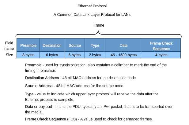
Ethernet Protocol for LANs
Ethernet is a family of networking technologies that are defined in the IEEE 802.2 and 802.3 standards. Ethernet standards define both the Layer 2 protocols and the Layer 1 technologies. Ethernet is the most widely used LAN technology and supports data bandwidths of 10, 100, 1000, or 10,000 Mbps. The basic frame format and the IEEE sublayers of OSI Layers 1 and 2 remain consistent across all forms of Ethernet. However, the methods for detecting and placing data on the media vary with different implementations. Ethernet provides unacknowledged connectionless service over a shared media using CSMA/CD as the media access methods. Shared media requires that the Ethernet packet header use a Data Link layer address to identify the source and destination nodes. As with most LAN protocols, this address is referred to as the MAC address of the node. An Ethernet MAC address is 48 bits and is generally represented in hexadecimal format. The Ethernet frame has many fields, as shown in the figure. At the Data Link layer, the frame structure is nearly identical for all speeds of Ethernet. However, at the Physical layer, different versions of Ethernet place the bits onto the media differently. Ethernet II is the Ethernet frame format used in TCP/IP networks. Ethernet is such an important part of data networking, we have devoted a chapter to it. We also use it in examples throughout this series of courses.
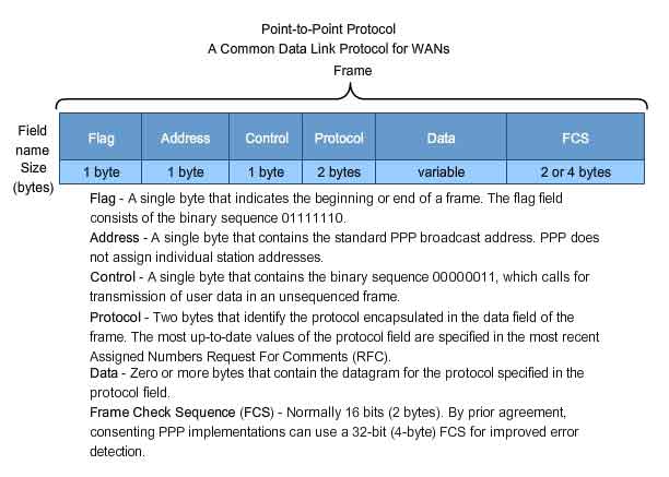
Point-to-Point Protocol for WANs
Point-to-Point Protocol (PPP) is a protocol used to deliver frames between two nodes. Unlike many Data Link layer protocols that are defined by electrical engineering organizations, the PPP standard is defined by RFCs. PPP was developed as a WAN protocol and remains the protocol of choice to implement many serial WANs. PPP can be used on various physical media, including twisted pair, fiber optic lines, and satellite transmission, as well as for virtual connections. PPP uses a layered architecture. To accommodate the different types of media, PPP establishes logical connections, called sessions, between two nodes. The PPP session hides the underlying physical media from the upper PPP protocol. These sessions also provide PPP with a method for encapsulating multiple protocols over a point-to-point link. Each protocol encapsulated over the link establishes its own PPP session. PPP also allows the two nodes to negotiate options within the PPP session. This includes authentication, compression, and multilink (the use of multiple physical connections).
Wireless Protocol for LANs
802.11 is an extension of the IEEE 802 standards. It uses the same 802.2 LLC and 48-bit addressing scheme as other 802 LANs, However there are many differences at the MAC sublayer and Physical layer. In a wireless environment, the environment requires special considerations. There is no definable physical connectivity; therefore, external factors may interfere with data transfer and it is difficult to control access. To meet these challenges, wireless standards have additional controls. The Standard IEEE 802.11, commonly referred to as Wi-Fi, is a contention-based system using a Carrier Sense Multiple Access/Collision Avoidance (CSMA/CA) media access process. CSMA/CA specifies a random backoff procedure for all nodes that are waiting to transmit. The most likely opportunity for medium contention is just after the medium becomes available. Making the nodes back off for a random period greatly reduces the likelihood of a collision. 802.11 networks also use Data Link acknowledgements to confirm that a frame is received successfully. If the sending station does not detect the acknowledgement frame, either because the original data frame or the acknowledgment was not received intact, the frame is retransmitted. This explicit acknowledgement overcomes interference and other radio-related problems. Other services supported by 802.11 are authentication, association (connectivity to a wireless device), and privacy (encryption).
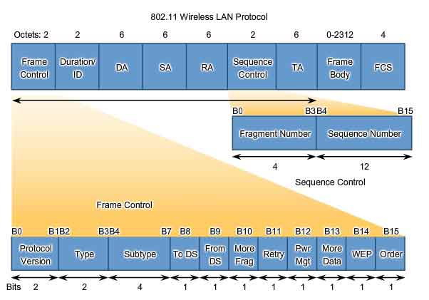
An 802.11 frame is shown in the figure. It contains these fields:
Protocol Version field - Version of 802.11 frame in use
Type and Subtype fields - Identifies one of three functions and sub functions of the frame: control, data, and management
To DS field - Set to 1 in data frames destined for the distribution system (devices in the wireless structure)
From DS field - Set to 1 in data frames exiting the distribution system
More Fragments field - Set to 1 for frames that have another fragment
Retry field - Set to 1 if the frame is a retransmission of an earlier frame
Power Management field - Set to 1 to indicate that a node will be in power-save mode
More Data field - Set to 1 to indicate to a node in power-save mode that more frames are buffered for that node
Wired Equivalent Privacy (WEP) field - Set to 1 if the frame contains WEP encrypted information for security
Order field - Set to 1 in a data type frame that uses Strictly Ordered service class (does not need reordering)
Duration/ID field - Depending on the type of frame, represents either the time, in microseconds, required to transmit the frame or an association identity (AID) for the station that transmitted the frame
Destination Address (DA) field - MAC address of the final destination node in the network
Source Address (SA) field - MAC address of the node the initiated the frame
Receiver Address (RA) field - MAC address that identifies the wireless device that is the immediate recipient of the frame
Transmitter Address (TA) field - MAC address that identifies the wireless device that transmitted the frame
Sequence Number field - Indicates the sequence number assigned to the frame; retransmitted frames are identified by duplicate sequence numbers
Fragment Number field - Indicates the number for each fragment of a frame
Frame Body field - Contains the information being transported; for data frames, typically an IP packet
FCS field - Contains a 32-bit cyclic redundancy check (CRC) of the frame
PPP protocol: http://www.ietf.org/rfc/rfc1661.txt?number=1661
PPP Vendor Extensions: http://www.ietf.org/rfc/rfc2153.txt?number=2153
Putting it All Together
Follow Data Through an Internetwork
The figure on the next page presents a simple data transfer between two hosts across an internetwork. We highlight the function of each layer during the communication. For this example we will depict an HTTP request between a client and a server. To focus on the data transfer process, we are omitting many elements that may occur in a real transaction. In each step we are only bringing attention to the major elements. Many parts of the headers are ignored, for example. We are assuming that all routing tables are converged and ARP tables are complete. Additionally, we are assuming that a TCP session is already established between the client and server. We will also assume that the DNS lookup for the WWW server is already cached at the client. In the WAN connection between the two routers, we are assuming that PPP has already established a physical circuit and has established a PPP session. On the next page, you can step through this communication. We encourage you to read each explanation carefully and study the operation of the layers for each device.