

OSI Network Layer
IPv4
Anatomia di un indirizzo IPv4
Network Layer - Communication from Host to Host
The Network layer, or OSI Layer 3, provides services to exchange the individual pieces of data over the network between identified end devices. To accomplish this end-to-end transport, Layer 3 uses four basic processes:
-
Addressing
- Encapsulation
- Routing
- Decapsulation
Addressing
First, the Network layer must provide a mechanism for addressing these end devices. If individual pieces of data are to be directed to an end device, that device must have a unique address. In an IPv4 network, when this address is added to a device, the device is then referred to as a host.
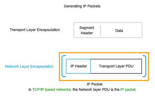
Encapsulation
Second, the Network layer must provide encapsulation. Not only must the devices be identified with an address, the individual pieces - the Network layer PDUs - must also contain these addresses. During the encapsulation process, Layer 3 receives the Layer 4 PDU and adds a Layer 3 header, or label, to create the Layer 3 PDU. When referring to the Network layer, we call this PDU a packet. When a packet is created, the header must contain, among other information, the address of the host to which it is being sent. This address is referred to as the destination address. The Layer 3 header also contains the address of the originating host. This address is called the source address. After the Network layer completes its encapsulation process, the packet is sent down to the Data Link layer to be prepared for transportation over the media.
Routing
Next, the Network layer must provide services to direct these packets to their destination host. The source and destination hosts are not always connected to the same network. In fact, the packet might have to travel through many different networks. Along the way, each packet must be guided through the network to reach its final destination. Intermediary devices that connect the networks are called routers. The role of the router is to select paths for and direct packets toward their destination. This process is known as routing. During the routing through an internetwork, the packet may traverse many intermediary devices. Each route that a packet takes to reach the next device is called a hop. As the packet is forwarded, its contents (the Transport layer PDU), remain intact until the destination host is reached.
Decapsulation
Finally, the packet arrives at the destination host and is processed at Layer 3. The host examines the destination address to verify that the packet was addressed to this device. If the address is correct, the packet is decapsulated by the Network layer and the Layer 4 PDU contained in the packet is passed up to the appropriate service at Transport layer. Unlike the Transport layer (OSI Layer 4), which manages the data transport between the processes running on each end host, Network layer protocols specify the packet structure and processing used to carry the data from one host to another host. Operating without regard to the application data carried in each packet allows the Network layer to carry packets for multiple types of communications between multiple hosts.
Network Layer Protocols
Protocols implemented at the Network layer that carry user data include:
-
Internet Protocol version 4 (IPv4)
- Internet Protocol version 6 (IPv6)
- Novell Internetwork Packet Exchange (IPX)
- AppleTalk
- Connectionless Network Service (CLNS/DECNet)
The Internet Protocol (IPv4 and IPv6) is the most widely-used Layer 3 data carrying protocol and will be the focus of this course. Discussion of the other protocols will be minimal.
The IP v4 Protocol - Example Network Layer Protocol
Role of IPv4
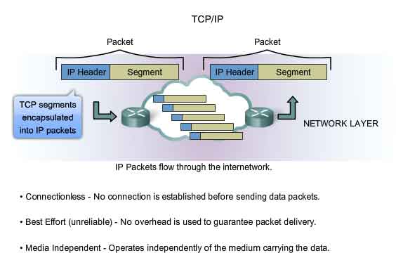
As shown in the figure, the Network layer services implemented by the TCP/IP protocol suite are the Internet Protocol (IP). Version 4 of IP (IPv4) is currently the most widely-used version of IP. It is the only Layer 3 protocol that is used to carry user data over the Internet and is the focus of the CCNA. Therefore, it will be the example we use for Network layer protocols in this course. IP version 6 (IPv6) is developed and being implemented in some areas. IPv6 will operate alongside IPv4 and may replace it in the future. The services provided by IP, as well as the packet header structure and contents, are specified by either IPv4 protocol or IPv6 protocol. These services and packet structure are used to encapsulate UDP datagrams or TCP segments for their trip across an internetwork. The characteristics of each protocol are different. Understanding these characteristics will allow you to understand the operation of the services described by this protocol. The Internet Protocol was designed as a protocol with low overhead. It provides only the functions that are necessary to deliver a packet from a source to a destination over an interconnected system of networks. The protocol was not designed to track and manage the flow of packets. These functions are performed by other protocols in other layers.
IPv4 basic characteristics:
-
Connectionless - No connection is established before sending data packets.
- est Effort (unreliable) - No overhead is used to guarantee packet delivery.
- Media Independent - Operates independently of the medium carrying the data.
The IP v4 Protocol - Connectionless
Connectionless Service
An example of connectionless communication is sending a letter to someone without notifying the recipient in advance. As shown in the figure, the postal service still takes the letter and delivers it to the recipient. Connectionless data communications works on the same principle. IP packets are sent without notifying the end host that they are coming. Connection-oriented protocols, such as TCP, require that control data be exchanged to establish the connection as well as additional fields in the PDU header. Because IP is connectionless, it requires no initial exchange of control information to establish an end-to-end connection before packets are forwarded, nor does it require additional fields in the PDU header to maintain this connection. This process greatly reduces the overhead of IP. Connectionless packet delivery may, however, result in packets arriving at the destination out of sequence. If out-of-order or missing packets create problems for the application using the data, then upper layer services will have to resolve these issues.
The IP v4 Protocol - Best Effort
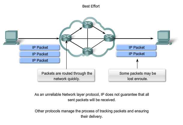
Best Effort Service (unreliable)
The IP protocol does not burden the IP service with providing reliability. Compared to a reliable protocol, the IP header is smaller. Transporting these smaller headers requires less overhead. Less overhead means less delay in delivery. This characteristic is desirable for a Layer 3 protocol. The mission of Layer 3 is to transport the packets between the hosts while placing as little burden on the network as possible. Layer 3 is not concerned with or even aware of the type of communication contained inside of a packet. This responsibility is the role of the upper layers as required. The upper layers can decide if the communication between services needs reliability and if this communication can tolerate the overhead reliability requires. IP is often referred to as an unreliable protocol. Unreliable in this context does not mean that IP works properly sometimes and does not function well at other times. Nor does it mean that it is unsuitable as a data communications protocol. Unreliable means simply that IP does not have the capability to manage, and recover from, undelivered or corrupt packets. Since protocols at other layers can manage reliability, IP is allowed to function very efficiently at the Network layer. If we included reliability overhead in our Layer 3 protocol, then communications that do not require connections or reliability would be burdened with the bandwidth consumption and delay produced by this overhead. In the TCP/IP suite, the Transport layer can choose either TCP or UDP, based on the needs of the communication. As with all layer isolation provided by network models, leaving the reliability decision to the Transport layer makes IP more adaptable and accommodating for different types of communication. The header of an IP packet does not include fields required for reliable data delivery. There are no acknowledgments of packet delivery. There is no error control for data. Nor is there any form of packet tracking; therefore, there is no possibility for packet retransmissions.
The IP v4 Protocol - Media Independent
Media Independent
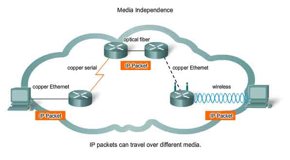
The Network layer is also not burdened with the characteristics of the media on which packets will be transported. IPv4 and IPv6 operate independently of the media that carry the data at lower layers of the protocol stack. As shown in the figure, any individual IP packet can be communicated electrically over cable, as optical signals over fiber, or wirelessly as radio signals. It is the responsibility of the OSI Data Link layer to take an IP packet and prepare it for transmission over the communications medium. This means that the transport of IP packets is not limited to any particular medium.
There is, however, one major characteristic of the media that the Network layer considers: the maximum size of PDU that each medium can transport. This characteristic is referred to as the Maximum Transmission Unit (MTU). Part of the control communication between the Data Link layer and the Network layer is the establishment of a maximum size for the packet. The Data Link layer passes the MTU upward to the Network layer. The Network layer then determines how large to create the packets. In some cases, an intermediary device - usually a router - will need to split up a packet when forwarding it from one media to a media with a smaller MTU. This process is called fragmenting the packet or fragmentation.
IP v4 Packet - Packaging the Transport Layer PDU
IPv4 encapsulates, or packages, the Transport layer segment or datagram so that the network can deliver it to the destination host. Click the steps in the figure to see this process. The IPv4 encapsulation remains in place from the time the packet leaves the Network layer of the originating host until it arrives at the Network layer of the destination host. The process of encapsulating data by layer enables the services at the different layers to develop and scale without affecting other layers. This means that transport layer segments can be readily packaged by existing Network layer protocols, such as IPv4 and IPv6 or by any new protocol that might be developed in the future. Routers can implement these different Network layer protocols to operate concurrently over a network to and from the same or different hosts. The routing performed by these intermediary devices only considers the contents of the packet header that encapsulates the segment. In all cases, the data portion of the packet - that is, the encapsulated Transport layer PDU - remains unchanged during the Network layer processes.
IP v4 Packet Header
As shown in the figure, an IPv4 protocol defines many different fields in the packet header. These fields contain binary values that the IPv4 services reference as they forward packets across the network.
This course will consider these 6 key fields:
-
IP Source Address
- IP Destination Address
- Time-to-Live (TTL)
- Type-of-Service (ToS)
- Protocol
- Fragment Offset
IP Destination Address
The IP Destination Address field contains a 32-bit binary value that represents the packet destination Network layer host address.
IP Source Address
The IP Source Address field contains a 32-bit binary value that represents the packet source Network layer host address.
Time-to-Live
The Time-to-Live (TTL) is an 8-bit binary value that indicates the remaining "life" of the packet. The TTL value is decreased by at least one each time the packet is processed by a router (that is, each hop). When the value becomes zero, the router discards or drops the packet and it is removed from the network data flow. This mechanism prevents packets that cannot reach their destination from being forwarded indefinitely between routers in a routing loop. If routing loops were permitted to continue, the network would become congested with data packets that will never reach their destination. Decrementing the TTL value at each hop ensures that it eventually becomes zero and that the packet with the expired TTL field will be dropped.
Protocol
This 8-bit binary value indicates the data payload type that the packet is carrying. The Protocol field enables the Network layer to pass the data to the appropriate upper-layer protocol.
Example values are:
-
01 ICMP
- 06 TCP
- 17 UDP
Type-of-Service
The Type-of-Service field contains an 8-bit binary value that is used to determine the priority of each packet. This value enables a Quality-of-Service (QoS) mechanism to be applied to high priority packets, such as those carrying telephony voice data. The router processing the packets can be configured to decide which packet it is to forward first based on the Type-of-Service value.
Fragment Offset
As mentioned earlier, a router may have to fragment a packet when forwarding it from one medium to another medium that has a smaller MTU. When fragmentation occurs, the IPv4 packet uses the Fragment Offset field and the MF flag in the IP header to reconstruct the packet when it arrives at the destination host. The fragment offset field identifies the order in which to place the packet fragment in the reconstruction.
More Fragments flag
The More Fragments (MF) flag is a single bit in the Flag field used with the Fragment Offset for the fragmentation and reconstruction of packets. The More Fragments flag bit is set, it means that it is not the last fragment of a packet. When a receiving host sees a packet arrive with the MF = 1, it examines the Fragment Offset to see where this fragment is to be placed in the reconstructed packet. When a receiving host receives a frame with the MF = 0 and a non-zero value in the Fragment offset, it places that fragment as the last part of the reconstructed packet. An unfragmented packet has all zero fragmentation information (MF = 0, fragment offset =0).
Don't Fragment flag
The Don't Fragment (DF) flag is a single bit in the Flag field that indicates that fragmentation of the packet is not allowed. If the Don't Fragment flag bit is set, then fragmentation of this packet is NOT permitted. If a router needs to fragment a packet to allow it to be passed downward to the Data Link layer but the DF bit is set to 1, then the router will discard this packet.
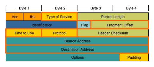
Version - Contains the IP version number (4).
Header Length (IHL) - Specifies the size of the packet header.
Packet Length - This field gives the entire packet size, including header and data, in bytes.
Identification - This field is primarily used for uniquely identifying fragments of an original IP packet.
Header Checksum - The checksum field is used for error checking the packet header.
Options - There is provision for additional fields in the IPv4 header to provide other services but these are rarely used.
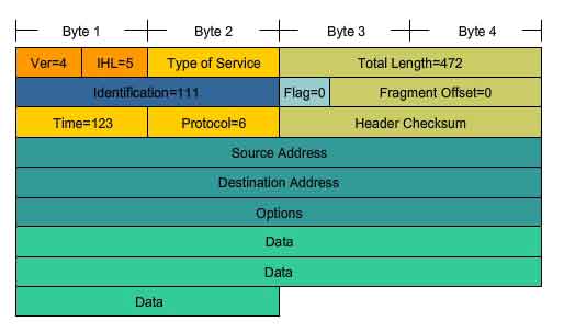
Typical IP Packet
The figure represents a complete IP packet with typical header field values.
Ver = 4; IP version.
IHL = 5; size of header in 32 bit words (4 bytes). This header is 5*4 = 20 bytes, the minimum valid size.
Total Length = 472; size of packet (header and data) is 472 bytes.
Identification = 111; original packet identifier (required if it is later fragmented).
Flag = 0; denotes packet can be fragmented if required.
Fragment Offset = 0; denotes that this packet is not currently fragmented (there is no offset).
Time to Live = 123; denotes the Layer 3 processing time in seconds before the packet is dropped (decremented by at least 1 every time a device processes the packet header).
Protocol = 6; denotes that the data carried by this packet is a TCP segment .
Networks - Dividing Hosts into Groups
Networks - Separating Hosts into Common Groups
One of the major roles of the Network layer is to provide a mechanism for addressing hosts. As the number of hosts on the network grows, more planning is required to manage and address the network.
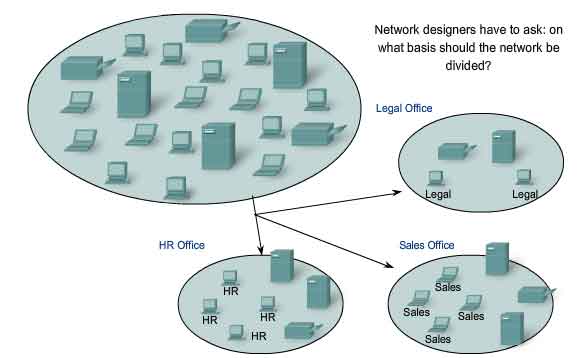
Dividing Networks
Rather than having all hosts everywhere connected to one vast global network, it is more practical and manageable to group hosts into specific networks. Historically, IP-based networks have their roots as one large network. As this single network grew, so did the issues related to its growth. To alleviate these issues, the large network was separated into smaller networks that were interconnected. These smaller networks are often called subnetworks or subnets. Network and subnet are terms often used interchangeably to refer to any network system made possible by the shared common communication protocols of the TCP/IP model. Similarly, as our networks grow, they may become too large to manage as a single network. At that point, we need to divide our network. When we plan the division of the network, we need to group together those hosts with common factors into the same network. As shown in the figure, networks can be grouped based on factors that include:
-
Geographic location
- Purpose
- Ownership
Grouping Hosts Geographically
We can group network hosts together geographically. Grouping hosts at the same location - such as each building on a campus or each floor of a multi-level building - into separate networks can improve network management and operation.
Grouping Hosts for Specific Purposes
Users who have similar tasks typically use common software, common tools, and have common traffic patterns. We can often reduce the traffic required by the use of specific software and tools by placing the resources to support them in the network with the users. The volume of network data traffic generated by different applications can vary significantly. Dividing networks based on usage facilitates the effective allocation of network resources as well as authorized access to those resources. Network professionals need to balance the number of hosts on a network with the amount of traffic generated by the users. For example, consider a business that employs graphic designers who use the network to share very large multimedia files. These files consume most of the available bandwidth for most of the working day. The business also employs salespersons who only logged in once a day to record their sales transactions, which generates minimal network traffic. In this scenario, the best use of network resources would be to create several small networks to which a few designers had access and one larger network that all the salespersons used.
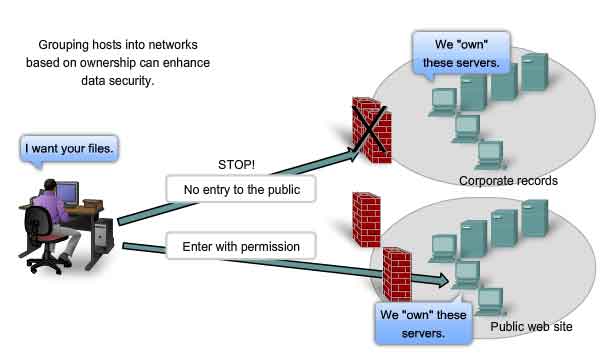
Grouping Hosts for Ownership
Using an organizational (company, department) basis for creating networks assists in controlling access to the devices and data as well as the administration of the networks. In one large network, it is much more difficult to define and limit the responsibility for the network personnel. Dividing hosts into separate networks provides a boundary for security enforcement and management of each network.
Network design:
http://www.cisco.com/univercd/cc/td/doc/cisintwk/idg4/nd2002.htm
Why Separate Hosts Into Networks? - Performance
As mentioned previously, as networks grow larger they present problems that can be at least partially alleviated by dividing the network into smaller interconnected networks.
Common issues with large networks are:
-
Performance degradation
- Security issues
- Address Management
Improving Performance
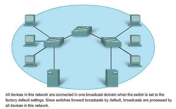
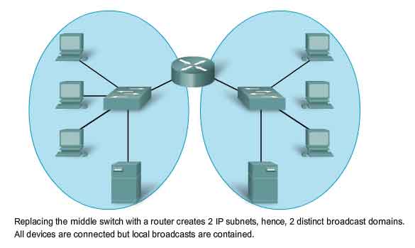
Large numbers of hosts connected to a single network can produce volumes of data traffic that may stretch, if not overwhelm, network resources such as bandwidth and routing capability. Dividing large networks so that hosts who need to communicate are grouped together reduces the traffic across the internetworks. In addition to the actual data communications between hosts, network management and control traffic (overhead) also increases with the number of hosts. A significant contributor to this overhead can be network broadcasts. A broadcast is a message sent from one host to all other hosts on the network. Typically, a host initiates a broadcast when information about another unknown host is required. Broadcasts are a necessary and useful tool used by protocols to enable data communication on networks. However, large numbers of hosts generate large numbers of broadcasts that consume network bandwidth. And because every other host has to process the broadcast packet it receives, the other productive functions that a host is performing are also interrupted or degraded. Broadcasts are contained within a network. In this context, a network is also known as a broadcast domain. Managing the size of broadcast domains by dividing a network into subnets ensures that network and host performances are not degraded to unacceptable levels.
Why Separate Hosts Into Networks? - Security
The IP-based network that has become the Internet originally had a small number of trusted users in U.S. government agencies and the research organizations that they sponsored. In this small community, security was not a significant issue. The situation has changed as individuals, businesses, and organizations have developed their own IP networks that link to the Internet. The devices, services, communications, and data are the property of those network owners. Network devices from other companies and organizations do not need to connect to their network. Dividing networks based on ownership means that access to and from resources outside each network can be prohibited, allowed, or monitored.
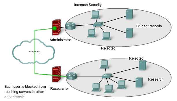
Internetwork access within a company or organization can be similarly secured. For example, a college network can be divided into administrative, research, and student subnetworks. Dividing a network based on user access is a means to secure communications and data from unauthorized access by users both within the organization and outside it. Security between networks is implemented in an intermediary device (a router or firewall appliance) at the perimeter of the network. The firewall function performed by this device permits only known, trusted data to access the network.
IP network security:
http://www.cisco.com/univercd/cc/td/doc/cisintwk/ics/cs003.htm
Why Separate Hosts Into Networks? - Address Management
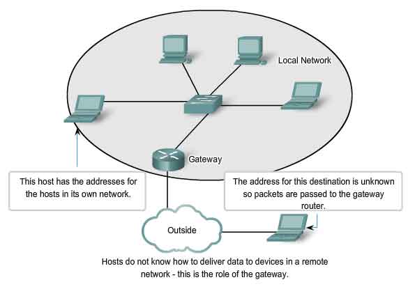
The Internet consists of millions of hosts, each of which is identified by its unique Network layer address. To expect each host to know the address of every other host would impose a processing burden on these network devices that would severely degrade their performance. Dividing large networks so that hosts who need to communicate are grouped together reduces the unnecessary overhead of all hosts needing to know all addresses. For all other destinations, the hosts only need to know the address of an intermediary device, to which they send packets for all other destinations addresses. This intermediary device is called a gateway. The gateway is a router on a network that serves as an exit from that network.
How Do We Separate Hosts Into Networks? - Hierarchical Addressing
To be able to divide networks, we need hierarchical addressing. A hierarchical address uniquely identifies each host. It also has levels that assist in forwarding packets across internetworks, which enables a network to be divided based on those levels. To support data communications between networks over internetworks, Network layer addressing schemes are hierarchical. Hierarchical Network layer addresses work in much the same way. Layer 3 addresses supply the network portion of the address. Routers forward packets between networks by referring only to the part of the Network layer address that is required to direct the packet toward the destination network. By the time the packet arrives at the destination host network, the whole destination address of the host will have been used to deliver the packet. If a large network needs to be divided into smaller networks, additional layers of addressing can be created. Using a hierarchical addressing scheme means that the higher levels of the address (similar to the country in the postal address) can be retained, with the middle level denoting the network addresses (state or city) and the lower level the individual hosts.
Dividing the Networks - Networks from Networks
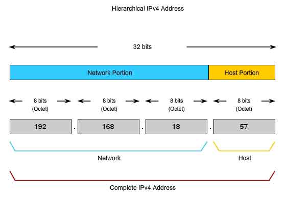
If a large network has to be divided, additional layers of addressing can be created. Using hierarchical addressing means that the higher levels of the address are retained; with a subnetwork level and then the host level. The logical 32-bit IPv4 address is hierarchical and is made up of two parts. The first part identifies the network and the second part identifies a host on that network. Both parts are required for a complete IP address. For convenience IPv4 addresses are divided in four groups of eight bits (octets). Each octet is converted to its decimal value and the complete address written as the four decimal values separated by a dot (period), f or example - 192.168.18.57
In this example, as the figure shows, the first three octets, (192.168.18), can identify the network portion of the address, and the last octet, (57) identifies the host. This is hierarchical addressing because the network portion indicates the network on which each unique host address is located. Routers only need to know how to reach each network, rather than needing to know the location of each individual host. With IPv4 hierarchical addressing, the network portion of the address for all hosts in a network is the same. To divide a network, the network portion of the address is extended to use bits from the host portion of the address. These borrowed host bits are then used as network bits to represent the different subnetworks within the range of the original network. Given that an IPv4 address is 32 bits, when host bits are used to divide a network the more subnetworks created results in fewer hosts for each subnetwork. Regardless of the number of subnetworks created however, all 32 bits are required to identify an individual host. The number of bits of an address used as the network portion is called the prefix length. For example if a network uses 24 bits to express the network portion of an address the prefix is said to be /24. In the devices in an IPv4 network, a separate 32-bit number called a subnet mask indicates the prefix. Extending the prefix length or subnet mask enables the creation of these subnetworks. In this way network administrators have the flexibility to divide networks to meet different needs, such as location, managing network performance, and security, while ensuring each host has a unique address.
Routing - How Our Data Packets are Handled
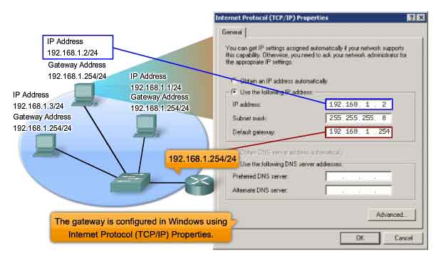
Device Parameters - Supporting Communication Outside Our Network
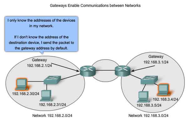
Within a network or a subnetwork, hosts communicate with each other without the need for any Network layer intermediary device. When a host needs to communicate with another network, an intermediary device, or router, acts as a gateway to the other network. As a part of its configuration, a host has a default gateway address defined. As shown in the figure, this gateway address is the address of a router interface that is connected to the same network as the host. Keep in mind that it is not feasible for a particular host to know the address of every device on the Internet with which it may have to communicate. To communicate with a device on another network, a host uses the address of this gateway, or default gateway, to forward a packet outside the local network. The router also needs a route that defines where to forward the packet next. This is called the next-hop address. If a route is available to the router, the router will forward the packet to the next-hop router that offers a path to the destination network.
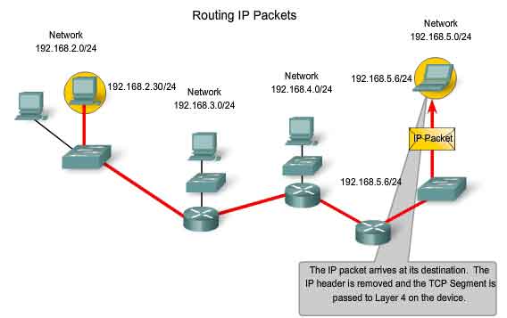
IP Packets - Carrying Data End to End
As you know, the role of the Network layer is to transfer data from the host that originates the data to the host that uses it. During encapsulation at the source host, an IP packet is constructed at Layer 3 to transport the Layer 4 PDU. If the destination host is in the same network as the source host, the packet is delivered between the two hosts on the local media without the need for a router. However, if the destination host and source host are not in the same network, the packet may be carrying a Transport layer PDU across many networks and through many routers. As it does, the information contained within is not altered by any routers when forwarding decisions are made. At each hop, the forwarding decisions are based on the information in the IP packet header. The packet with its Network Layer encapsulation also is basically intact throughout the complete process, from the source host to the destination host. If communication is between hosts in different networks, the local network delivers the packet from the source to its gateway router. The router examines the network portion of the packet destination address and forwards the packet to the appropriate interface. If the destination network is directly connected to this router, the packet is forwarded directly to that host. If the destination network is not directly connected, the packet is forwarded on to a second router that is the next-hop router. The packet forwarding then becomes the responsibility of this second router. Many routers or hops along the way may process the packet before reaching the destination.
A Gateway - The Way Out of Our Network
The gateway, also known as the default gateway, is needed to send a packet out of the local network. If the network portion of the destination address of the packet is different from the network of the originating host, the packet has to be routed outside the original network. To do this, the packet is sent to the gateway. This gateway is a router interface connected to the local network. The gateway interface has a Network layer address that matches the network address of the hosts. The hosts are configured to recognize that address as the gateway.
Default Gateway
The default gateway is configured on a host. On a Windows computer, the Internet Protocol (TCP/IP) Properties tools are used to enter the default gateway IPv4 address. Both the host IPv4 address and the gateway address must have the same network (and subnet, if used) portion of their respective addresses.
Host gateway configuration:
http://www.microsoft.com/technet/community/columns/cableguy/cg0903.mspx
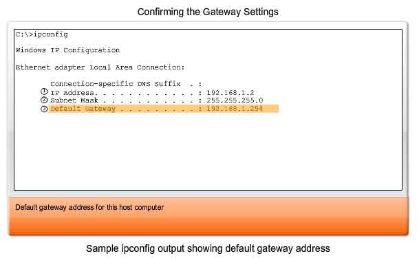
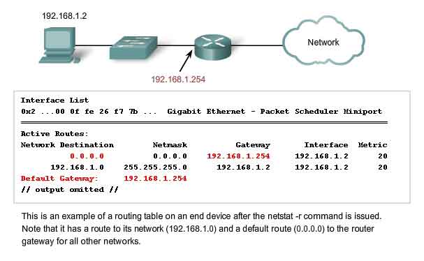
As shown in the figure, the IP address of the default gateway of a host can be viewed by issuing the ipconfig or route commands at the command line of a Windows computer. The route command is also used in a Linux or UNIX host.
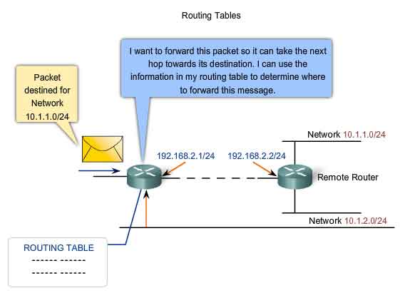
No packet can be forwarded without a route. Whether the packet is originating in a host or being forwarded by an intermediary device, the device must have a route to identify where to forward the packet. A host must either forward a packet to the host on the local network or to the gateway, as appropriate. To forward the packets, the host must have routes that represent these destinations. A router makes a forwarding decision for each packet that arrives at the gateway interface. This forwarding process is referred to as routing. To forward a packet to a destination network, the router requires a route to that network. If a route to a destination network does not exist, the packet cannot be forwarded. The destination network may be a number of routers or hops away from the gateway. The route to that network would only indicate the next-hop router to which the packet is to be forwarded, not the final router. The routing process uses a route to map the destination network address to the next hop and then forwards the packet to this next-hop address.
A Route - The Path to a Network
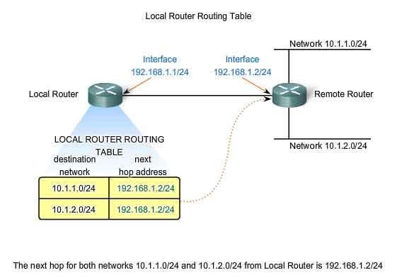
A route for packets for remote destinations is added using the default gateway address as the next hop. Although it is not usually done, a host can also have routes manually added through configurations. Like end devices, routers also add routes for the connected networks to their routing table. When a router interface is configured with an IP address and subnet mask, the interface becomes part of that network. The routing table now includes that network as a directly connected network. All other routes, however, must be configured or acquired via a routing protocol. To forward a packet the router must know where to send it. This information is available as routes in a routing table. The routing table stores information about connected and remote networks. Connected networks are directly attached to one of the router interfaces. These interfaces are the gateways for the hosts on different local networks. Remote networks are networks that are not directly connected to the router. Routes to these networks can be manually configured on the router by the network administrator or learned automatically using dynamic routing protocols.
Routes in a routing table have three main features:
-
Destination network
- Next-hop
- Metric
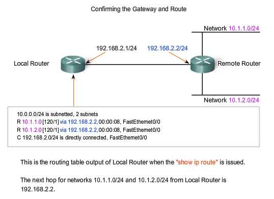
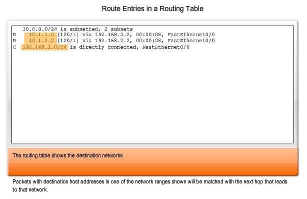
The router matches the destination address in the packet header with the destination network of a route in the routing table and forwards the packet to the next-hop router specified by that route. If there are two or more possible routes to the same destination, the metric is used to decide which route appears on the routing table. As shown in the figure, the routing table in a Cisco router can be examined with the show ip route command.
Note: The routing process and the role of metrics are the subject of a later course and will be covered in detail there.
As you know, packets cannot be forwarded by the router without a route. If a route representing the destination network is not on the routing table, the packet will be dropped (that is, not forwarded). The matching route could be either a connected route or a route to a remote network. The router may also use a default route to forward the packet. The default route is used when the destination network is not represented by any other route in the routing table.
Host Routing Table
A host creates the routes used to forward the packets it originates. These routes are derived from the connected network and the configuration of the default gateway. Hosts automatically add all connected networks to the routes. These routes for the local networks allow packets to be delivered to hosts that are connected to these networks. Hosts also require a local routing table to ensure that Network layer packets are directed to the correct destination network. Unlike the routing table in a router, which contains both local and remote routes, the local table of the host typically contains its direct connection or connections to the network and its own default route to the gateway. Configuring the default gateway address on the host creates the local default route. As shown in the figure, the routing table of a computer host can be examined at the command line by issuing the netstat -r, route, or route PRINT commands. In some circumstances, you may want to indicate more specific routes from a host. You can use the following options for the route command to modify the routing table contents:
route ADD
route DELETE
route CHANGE
The Destination Network
Routing Table Entries
The destination network shown in a routing table entry, called a route, represents a range of host addresses and sometimes a range of network and host addresses. The hierarchical nature of Layer 3 addressing means that one route entry could refer to a large general network and another entry could refer to a subnet of that same network. When forwarding a packet, the router will select the most specific route. Returning to the earlier postal addressing example, consider sending the same letter from Japan to 170 West Tasman Drive San Jose, California USA. Which address would you use: "USA" or "San Jose California USA" or "West Tasman Drive San Jose, California USA" or "170 West Tasman Drive San Jose, California USA"? The fourth and most specific address would be used. However, for another letter where the street number was unknown, the third option would provide the best address match.
In the same way, a packet destined to the subnet of a larger network would be routed using the route to the subnet. However, a packet addressed to a different subnet within the same larger network would be routed using the more general entry. As shown in the figure, if a packet arrives at a router with the destination address of 10.1.1.55, the router forwards the packet to a next-hop router associated with a route to network 10.1.1.0. If a route to 10.1.1.0 is not listed on the routing, but a route to 10.1.0.0 is available, the packet is forwarded to the next-hop router for that network. Therefore, the precedence of route selection for the packet going to 10.1.1.55 would be:
1. 10.1.1.0
2. 10.1.0.0
3. 10.0.0.0
4. 0.0.0.0 (Default route if configured)
5. Dropped
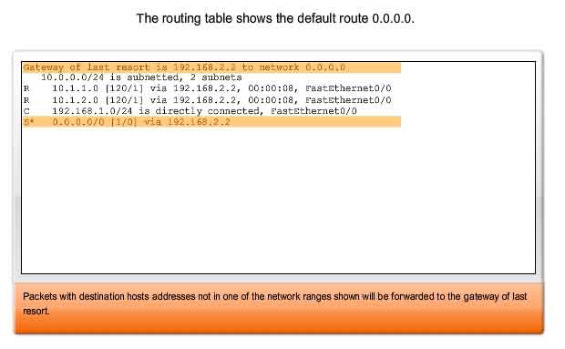
Default Route
A router can be configured to have a default route. A default route is a route that will match all destination networks. In IPv4 networks, the address 0.0.0.0 is used for this purpose. The default route is used to forward packets for which there is no entry in the routing table for the destination network. Packets with a destination network address that does not match a more specific route in the routing table are forwarded to the next-hop router associated with the default route.
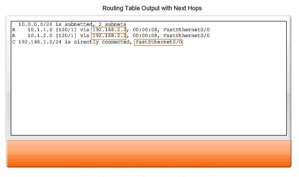
The Next Hop - Where the Packet Goes Next
A next-hop is the address of the device that will process the packet next. For a host on a network, the address of the default gateway (router interface) is the next-hop for all packets destined for another network. In the routing table of a router, each route lists a next hop for each destination address that is encompassed by the route. As each packet arrives at a router, the destination network address is examined and compared to the routes in the routing table. When a matching route is determined, the next hop address for that route is used to forward of the packet toward its destination. The router then forwards the packet out the interface to which the next-hop router is connected. The next-hop router is the gateway to networks beyond that intermediate destination. Networks directly connected to a router have no next-hop address because there is no intermediate Layer 3 device between the router and that network. The router can forward packets directly out the interface onto that network to the destination host. Some routes can have multiple next-hops. This indicates that there are multiple paths to the same destination network. These are parallel routes that the router can use to forward packets.
Packet Forwarding - Moving the Packet Toward its Destination
Routing is done packet-by-packet and hop-by-hop. Each packet is treated independently in each router along the path. At each hop, the router examines the destination IP address for each packet and then checks the routing table for forwarding information.
The router will do one of three things with the packet:
-
Forward it to the next-hop router
- Forward it to the destination host
- Drop it
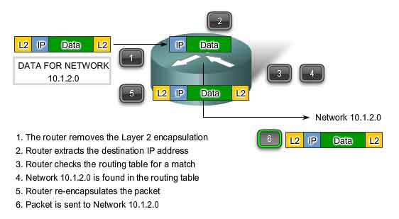
Packet Examination
As an intermediary device, a router processes the packet at the Network layer. However, packets that arrive at a router's interfaces are encapsulated as a Data Link layer (Layer 2) PDU. As show in the figure, the router first discards the Layer 2 encapsulation so that the packet can be examined.
Next Hop Selection
In the router, the destination address in a packet header is examined. If a matching route in the routing table shows that the destination network is directly connected to the router, the packet is forwarded to the interface to which that network is connected. In this case, there is no next-hop. To be placed onto the connected network, the packet has to be first re-encapsulated by the Layer 2 protocol and then forwarded out the interface. If the route matching the destination network of the packet is a remote network, the packet is forwarded to the indicated interface, encapsulated by the Layer 2 protocol, and sent to the next-hop address.
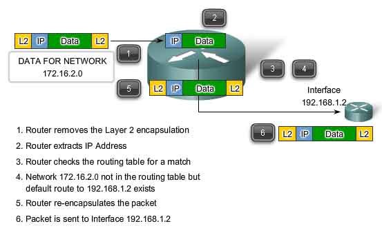
Using the Default Route
As shown in the figure, if the routing table does not contain a more specific route entry for an arriving packet, the packet is forwarded to the interface indicated by a default route, if one exists. At this interface, the packet is encapsulated by the Layer 2 protocol and sent to the next-hop router. The default route is also known as the Gateway of Last Resort. This process may occur a number of times until the packet reaches its destination network. The router at each hop knows only the address of the next-hop; it does not know the details of the pathway to the remote destination host. Furthermore, not all packets going to the same destination will be forwarded to the same next-hop at each router. Routers along the way may learn new routes while the communication is taking place and forward later packets to different next-hops. Default routes are important because the gateway router is not likely to have a route to every possible network on the Internet. If the packet is forwarded using a default route, it should eventually arrive at a router that has a specific route to the destination network. This router may be the router to which this network is attached. In this case, this router will forward the packet over the local network to the destination host.
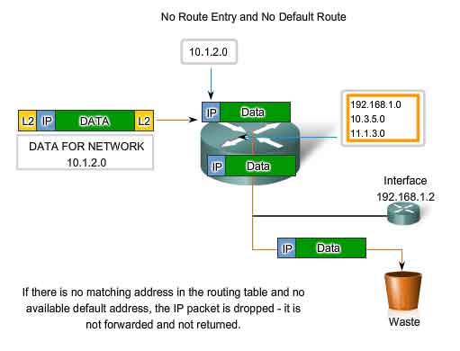
As a packet passes through the hops in the internetwork, all routers require a route to forward a packet. If, at any router, no route for the destination network is found in the routing table and there is no default route, that packet is dropped. IP has no provision to return a packet to the previous router if a particular router has nowhere to send the packet. Such a function would detract from the protocol's efficiency and low overhead. Other protocols are used to report such errors.
Routing Processes: How Routes are Learned
Routing Protocols - Sharing the Routes
Routing requires that every hop, or router, along the path to a packet's destination have a route to forward the packet. Otherwise, the packet is dropped at that hop. Each router in a path does not need a route to all networks. It only needs to know the next hop on the path to the packet's destination network. The routing table contains the information that a router uses in its packet forwarding decisions. For the routing decisions, the routing table needs to represent the most accurate state of network pathways that the router can access. Out-of-date routing information means that packets may not be forwarded to the most appropriate next-hop, causing delays or packet loss. This route information can be manually configured on the router or learned dynamically from other routers in the same internetwork. After the interfaces of a router are configured and operational, the network associated with each interface is installed in the routing table as a directly connected route.
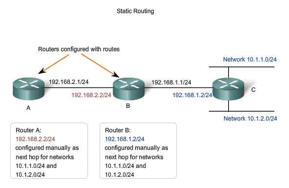
Static Routing
Routes to remote networks with the associated next hops can be manually configured on the router. This is known as static routing. A default route can also be statically configured. If the router is connected to a number of other routers, knowledge of the internetworking structure is required. To ensure that the packets are routed to use the best possible next hops, each known destination network needs to either have a route or a default route configured. Because packets are forwarded at every hop, every router must be configured with static routes to next hops that reflect its location in the internetwork. Further, if the internetwork structure changes or if new networks become available, these changes have to be manually updated on every router. If updating is not done in a timely fashion, the routing information may be incomplete or inaccurate, resulting in packet delays and possible packet loss.
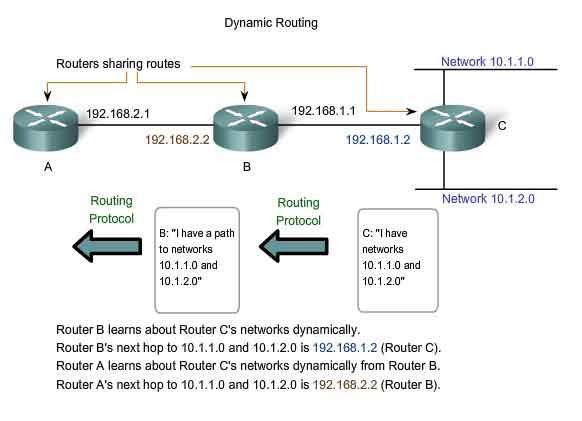
Dynamic Routing
Although it is essential for all routers in an internetwork to have up-to-date extensive route knowledge, maintaining the routing table by manual static configuration is not always feasible. Therefore, dynamic routing protocols are used. Routing protocols are the set of rules by which routers dynamically share their routing information. As routers become aware of changes to the networks for which they act as the gateway, or changes to links between routers, this information is passed on to other routers. When a router receives information about new or changed routes, it updates its own routing table and, in turn, passes the information to other routers. In this way, all routers have accurate routing tables that are updated dynamically and can learn about routes to remote networks that are many hops way. An example of router sharing routes is shown in the figure.
Common routing protocols are:
-
Routing Information Protocol (RIP)
- Enhanced Interior Gateway Routing Protocol (EIGRP)
- Open Shortest Path First (OSPF)
Although routing protocols provide routers with up-to-date routing tables, there are costs. First, the exchange of route information adds overhead that consumes network bandwidth. This overhead can be an issue, particularly for low bandwidth links between routers. Second, the route information that a router receives is processed extensively by protocols such as EIGRP and OSPF to make routing table entries. This means that routers employing these protocols must have sufficient processing capacity to both implement the protocol's algorithms and to perform timely packet routing and forwarding. Static routing does not produce any network overhead and places entries directly into the routing table; no processing is required by the router. The cost for static routing is administrative - the manual configuration and maintenance of the routing table to ensure efficient and effective routing. In many internetworks, a combination of static, dynamic, and default routes are used to provide the necessary routes. The configuration of routing protocols on routers is an integral component of the CCNA and will be covered extensively by a later course.
Routing basics:
http://www.cisco.com/univercd/cc/td/doc/cisintwk/ito_doc/routing.htm
Introduction to internetworking:
http://www.cisco.com/univercd/cc/td/doc/cisintwk/ito_doc/introint.htm