

Configuring and Testing Your Network
Configuring Cisco devices - IOS basics
Cisco IOS
Similar to a personal computer, a router or switch cannot function without an operating system. Without an operating system, the hardware does not have any capabilities. The Cisco Internetwork Operating System (IOS) is the system software in Cisco devices. It is the core technology that extends across most of the Cisco product line. The Cisco IOS is used for most Cisco devices regardless of the size and type of the device. It is used for routers, LAN switches, small Wireless Access Points, large routers with dozens of interfaces, and many other devices.
The Cisco IOS provides devices with the following network services:
-
Basic routing and switching functions
- Reliable and secure access to networked resources
- Network scalability
The IOS operational details vary on different internetworking devices, depending on the device's purpose and feature set. The services provided by the Cisco IOS are generally accessed using a command line interface (CLI). The features accessible via the CLI vary based on the version of the IOS and the type of device. The IOS file itself is several megabytes in size and is stored in a semi-permanent memory area called flash. Flash memory provides non-volatile storage. This means that the contents of the memory are not lost when the device loses power. Even though the contents are not lost they can be changed or overwritten if needed. Using flash memory allows the IOS to be upgraded to newer versions or to have new features added. In many router architectures, the IOS is copied into RAM when the device is powered on and the IOS runs from RAM when the device is operating. This function increases the performance of the device.
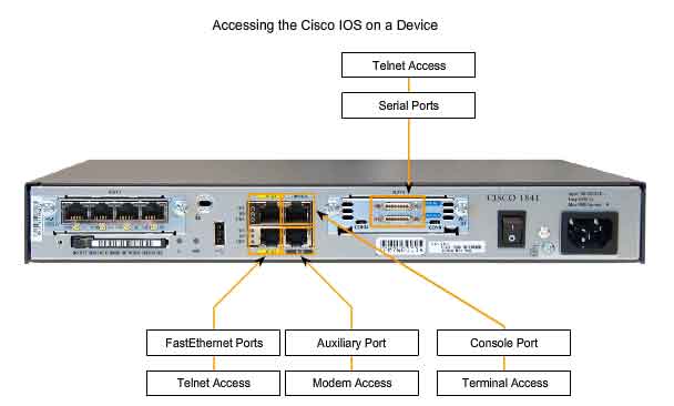
Access Methods
There are several ways to access the CLI environment. The most usual methods are:
-
Console
- Telnet or SSH
- AUX port
Console
The CLI can be accessed through a console session, also known as the CTY line. A console uses a low speed serial connection to directly connect a computer or terminal to the console port on the router or switch. The console port is a management port that provides out-of-band access to a router. The console port is accessible even if no networking services have been configured on the device. The console port is often used to access a device when the networking services have not been started or have failed.
Examples of console use are:
-
The initial configuration of the network device
- Disaster recovery procedures and troubleshooting where remote access is not possible
- Password recovery procedures
When a router is first placed into service, networking parameters have not been configured. Therefore, the router cannot communicate via a network. To prepare for the initial startup and configuration, a computer running terminal emulation software is connected to the console port of the device. Configuration commands for setting up the router can be entered on the connected computer. During operation, if a router cannot be accessed remotely, a connection to the console can enable a computer to determine the status of the device. By default, the console conveys the device startup, debugging, and error messages. For many IOS devices, console access does not require any form of security, by default. However, the console should be configured with passwords to prevent unauthorized device access. In the event that a password is lost, there is a special set of procedures for bypassing the password and accessing the device. The device should be located in a locked room or equipment rack to prevent physical access.
Telnet and SSH
A method for remotely accessing a CLI session is to telnet to the router. Unlike the console connection, Telnet sessions require active networking services on the device. The network device must have at least one active interface configured with a Layer 3 address, such as an IPv4 address. Cisco IOS devices include a Telnet server process that launches when the device is started. The IOS also contains a Telnet client. A host with a Telnet client can access the vty sessions running on the Cisco device. For security reasons, the IOS requires that the Telnet session use a password, as a minimum authentication method. The methods for establishing logins and passwords will be discussed in a later section. The Secure Shell (SSH) protocol is a more secure method for remote device access. This protocol provides the structure for a remote login similar to Telnet, except that it utilizes more secure network services. SSH provides stronger password authentication than Telnet and uses encryption when transporting session data. The SSH session encrypts all communications between the client and the IOS device. This keeps the user ID, password, and the details of the management session private. As a best practice, always use SSH in place of Telnet whenever possible. Most newer versions of the IOS contain an SSH server. In some devices, this service is enabled by default. Other devices require the SSH server to be enabled. IOS devices also include an SSH client that can be used to establish SSH sessions with other devices. Similarly, you can use a remote computer with an SSH client to start a secure CLI session. SSH client software is not provided by default on all computer operating systems. You may need to acquire, install, and configure SSH client software for your computer.
AUX
Another way to establish a CLI session remotely is via a telephone dialup connection using a modem connected to the router's AUX port. Similar to the console connection, this method does not require any networking services to be configured or available on the device. The AUX port can also be used locally, like the console port, with a direct connection to a computer running a terminal emulation program. The console port is required for the configuration of the router, but not all routers have an auxiliary port. The console port is also preferred over the auxiliary port for troubleshooting because it displays router startup, debugging, and error messages by default. Generally, the only time the AUX port is used locally instead of the console port is when there are problems using the console port, such as when certain console parameters are unknown.
Configuration Files
Network devices depend on two types of software for their operation: operating system and configuration. Like the operating system in any computer, the operating system facilitates the basic operation of the device's hardware components. Configuration files contain the Cisco IOS software commands used to customize the functionality of a Cisco device. Commands are parsed (translated and executed) by the Cisco IOS software when the system is booted (from the startup-config file) or when commands are entered in the CLI while in configuration mode. A network administrator creates a configuration that defines the desired functionality of a Cisco device. The configuration file is typically a few hundred to a few thousand bytes in size.
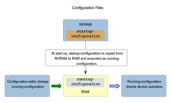
Types of Configuration Files
A Cisco network device contains two configuration files:
-
The running configuration file - used during the current operation of the device
- The startup configuration file - used as the backup configuration and is loaded when the device is started
A configuration file may also be stored remotely on a server as a backup.
Startup Configuration File
The startup configuration file (startup-config) is used during system startup to configure the device. The startup configuration file or startup-config file is stored in non-volatile RAM (NVRAM). Since NVRAM is non-volatile, when the Cisco device is turned off, the file remains intact. The startup-config files are loaded into RAM each time the router is started or reloaded. Once the configuration file is loaded into RAM, it is considered the running configuration or running-config.
Running Configuration
Once in RAM, this configuration is used to operate the network device. The running configuration is modified when the network administrator performs device configuration. Changes to the running configuration will immediately affect the operation of the Cisco device. After making any changes, the administrator has the option of saving those changes back to the startup-config file so that they will be used the next time the device restarts. Because the running configuration file is in RAM, it is lost if the power to the device is turned off or if the device is restarted. Changes made to the running-config file will also be lost if they are not saved to the startup-config file before the device is powered down.
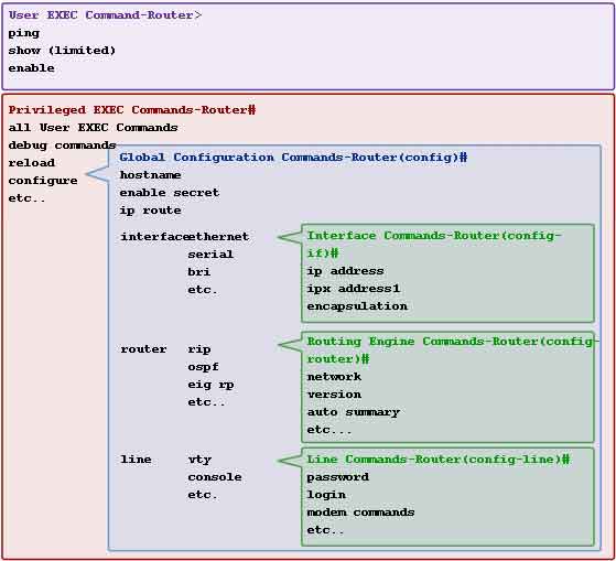
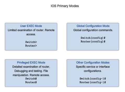
Cisco IOS Modes
The Cisco IOS is designed as a modal operating system. The term modal describes a system where there are different modes of operation, each having its own domain of operation. The CLI uses a hierarchical structure for the modes.
In order from top to bottom, the major modes are:
-
User executive mode
- Privileged executive mode
- Global configuration mode
- Other specific configuration modes
Each mode is used to accomplish particular tasks and has a specific set of commands that are available when in that mode. For example, to configure a router interface, the user must enter interface configuration mode. All configurations that are entered in interface configuration mode apply only to that interface. Some commands are available to all users; others can be executed only after entering the mode in which that command is available. Each mode is distinguished with a distinctive prompt, and only commands that are appropriate for that mode are allowed. The hierarchical modal structure can be configured to provide security. Different authentication can be required for each hierarchal mode. This controls the level of access that network personnel can be granted.
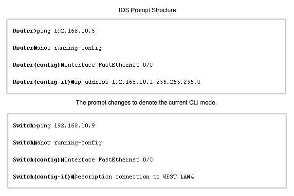
Command Prompts
When using the CLI, the mode is identified by the command-line prompt that is unique to that mode. The prompt is composed of the words and symbols on the line to the left of the entry area. The word prompt is used because the system is prompting you to make an entry. By default, every prompt begins with the device name. Following the name, the remainder of the prompt indicates the mode. For example, the default prompt for the global configuration mode on a router would be:
Router(config)#
As commands are used and modes are changed, the prompt changes to reflect the current context, as shown in the figure.
Primary Modes
The two primary modes of operation are:
-
User EXEC
- Privileged EXEC
As a security feature, the Cisco IOS software separates the EXEC sessions into two access modes. These two primary access modes are used within the Cisco CLI hierarchical structure. Each mode has similar commands. However, the privileged EXEC mode has a higher level of authority in what it allows to be executed.
User Executive Mode
The user executive mode, or user EXEC for short, has limited capabilities but is useful for some basic operations. The user EXEC mode is at the top of the modal hierarchical structure. This mode is the first entrance into the CLI of an IOS router. The user EXEC mode allows only a limited number of basic monitoring commands. This is often referred to as view-only mode. The user EXEC level does not allow the execution of any commands that might change the configuration of the device. By default, there is no authentication required to access the user EXEC mode from the console. It is a good practice to ensure that authentication is configured during the initial configuration. The user EXEC mode is identified by the CLI prompt that ends with the > symbol. This is an example that shows the > symbol in the prompt:
Switch>
Privileged EXEC Mode
The execution of configuration and management commands requires that the network administrator use the privileged EXEC mode, or a specific mode further down the hierarchy. The privileged EXEC mode can be identified by the prompt ending with the # symbol.
Switch#
By default, privileged EXEC does not require authentication. It is a good practice to ensure that authentication is configured. Global configuration mode and all other more specific configuration modes can only be reached from the privileged EXEC mode. In a later section of this chapter, we will examine device configuration and some of the configuration modes.
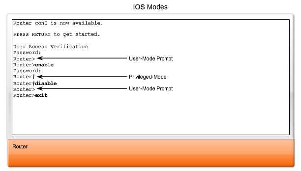
Moving between the User EXEC and Privileged EXEC Modes
The enable and disable commands are used to change the CLI between the user EXEC mode and the privileged EXEC mode, respectively. In order to access the privileged EXEC mode, use the enable command. The privileged EXEC mode is sometimes called the enable mode.
The syntax for entering the enable command is:
Router>enable
This command is executed without the need for an argument or keyword. Once <Enter> is pressed, the router prompt changes to:
Router#
The # at the end of the prompt indicates that the router is now in privileged EXEC mode.
If password authentication has been configured for the privileged EXEC mode, the IOS prompts for the password.
For example:
Router>enable
Password:
Router#
The disable command is used to return from the privileged EXEC to the user EXEC mode.
For example:
Router#disable
Router>
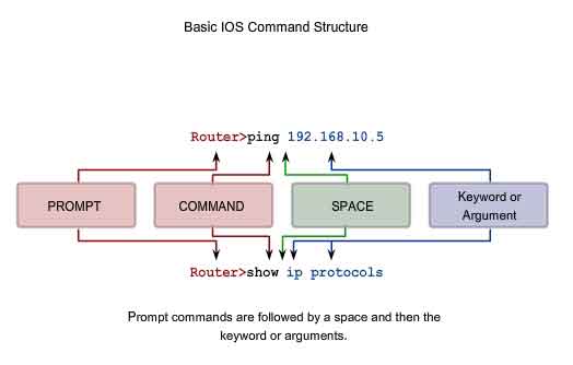
Basic IOS Command Structure
Each IOS command has specific format or syntax and is executed at the appropriate prompt. The general syntax for a command is the command followed by any appropriate keywords and arguments. Some commands include a subset of keywords and arguments that provide additional functionality. The figure shows these parts of a command. The command is the initial word or words entered in the command line. The commands are not case-sensitive. Following the command are one or more keywords and arguments. The keywords describe specific parameters to the command interpreter. For example, the show command is used to display information about the device. This command has various keywords that can be used to define what particular output should be displayed. For example:
Switch#show running-config
The command show is followed by the keyword running-config. The keyword specifies that the running configuration is to be displayed as the output. A command might require one or more arguments. Unlike a keyword, an argument is generally not a predefined word. An argument is a value or variable defined by the user. As an example, when applying a description to an interface with the description command, enter a line such as this:
Switch(config-if)#description MainHQ Office Switch
The command is: description. The argument is: MainHQ Office Switch. The user defines the argument. For this command, the argument can be any text string of up to 80 characters. After entering each complete command, including any keywords and arguments, press the <Enter> key to submit the command to the command interpreter.
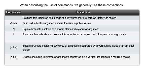
IOS Conventions
The figure and the following examples demonstrate some conventions for documenting IOS commands.
For the ping command:
Format:
Router>ping IP address
Example with values:
Router>ping 10.10.10.5
The command is ping and the argument is the IP address.
Similarly, the syntax for entering the traceroute command is:
Format:
Switch>traceroute IP address
Example with values:
Switch>traceroute 192.168.254.254
The command is traceroute and the argument is the IP address.
Commands are used to execute an action, and the keywords are used to identify where or how to execute the command.
For another example, return to examining the description command.
Format:
Router(config-if)#description string
Example with values:
Switch(config-if)#description Interface to Building a LAN
The command is description , and the argument applied to the interface is the text string, Interface to Building a LAN. Once the command is executed, that description will be applied to the particular interface.
Using CLI Help
The IOS has several forms of help available:
-
Context-sensitive help
- Command Syntax Check
- Hot Keys and Shortcuts
Context-Sensitive Help
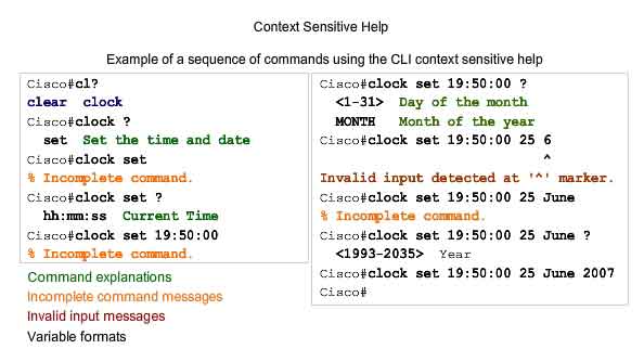
The context-sensitive help provides a list of commands and the arguments associated with those commands within the context of the current mode. To access context-sensitive help, enter a question mark, ?, at any prompt. There is an immediate response without the need to use the <Enter> key. One use of context-sensitive help is to get a list of available commands. This can be used when you are unsure of the name for a command or you want to see if the IOS supports a particular command in a particular mode.
For example, to list the commands available at the user EXEC level, type a question mark ? at the Router> prompt.
Another use of context-sensitive help is to display a list of commands or keywords that start with a specific character or characters. After entering a character sequence, if a question mark is immediately entered-without a space-the IOS will display a list of commands or keywords for this context that start with the characters that were entered. For example, enter sh? to get a list of commands that begin with the character sequence sh. A final type of context-sensitive help is used to determine which options, keywords, or arguments are matched with a specific command. When entering a command, enter a space followed by a ? to determine what can or should be entered next. As shown in the figure, after entering the command clock set 19:50:00, we can enter the ? to determine the options or keywords that fit with this command.
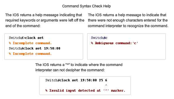
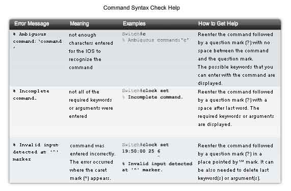
Command Syntax Check
When a command is submitted by pressing the <Enter> key, the command line interpreter parses the command from left to right to determine what action is being requested. The IOS generally only provides negative feedback. If the interpreter understands the command, the requested action is executed and the CLI returns to the appropriate prompt. However, if the interpreter cannot understand the command being entered, it will provide feedback describing what is wrong with the command. There are three different types of error messages:
-
Ambiguous command
- Incomplete command
- Incorrect command
Hot Keys and Shortcuts
The IOS CLI provides hot keys and shortcuts that make configuring, monitoring, and troubleshooting easier.
Here is show most of the shortcuts. The following are worthy of special note:
-
Tab - Completes the remainder of the command or keyword
- Backspace – Erases the character to the left of the cursor
- Ctrl-D – Erases the character at the cursor
- Ctrl-K – Erases all characters from the cursor to the end of the command line
- Esc D – Erases all characters from the cursor to the end of the word
- Ctrl-U or Ctrl-X – Erases all characters from back to the beginning of the command line
- Ctrl-W – Erases the word to the left of the cursor
- Ctrl-A – Moves the cursor to the beginning of the line
- Left Arrow or Ctrl-B – Moves the cursor one character to the left
- Esc B – Moves the cursor back one word to the left
- Esc F – Moves the cursor forward one word to the right
- Right Arrow or Ctrl-F – Moves the cursor one character to the right
- Ctrl-E – Moves the cursor to the end of command line
- Up Arrow or CTRL-P Recalls command in the history buffer, beginning with the most recent commands
- Ctrl-R or Ctrl-I or Ctrl-L – Redisplays the system prompt and command line after a console message is received
- Ctrl-R - Redisplays a line
- Ctrl-Z - Exits configuration mode and returns to the EXEC
- Down Arrow - Allows user to scroll forward through former commands
- Up Arrow - Allows user to scroll backward through former commands
- Ctrl-Shift-6 - Allows the user to interrupt an IOS process such as ping or traceroute
- Ctrl-C - Aborts the current command and exits the configuration mode
Examining these in more detail:
Tab - Tab complete is used to complete the remainder of abbreviated commands and parameters if the abbreviation contains enough letters to be different from any other currently available commands or parameters. When enough of the command or keyword has been entered to appear unique, press the Tab key and the CLI will display the rest of the command or keyword. This is a good technique to use when you are learning because it allows you to see the full word used for the command or keyword.
Ctrl-R - Redisplay line will refresh the line just typed. Use Ctrl-R to redisplay the line. For example, you may find that the IOS is returning a message to the CLI just as you are typing a line. You can use Ctrl-R to refresh the line and avoid having to retype it.
In this example, a message regarding a failed interface is returned in the middle of a command.
Switch#show mac-
16w4d: %LINK-5-CHANGED: Interface FastEthernet0/10, changed state to down
16w4d: %LINEPROTO-5-UPDOWN: Line protocol on Interface FastEthernet0/10, changed state to down
To redisplay to line that you were typing use Ctrl-R:
Switch#show mac
Ctrl-Z - Exit configuration mode. To leave a configuration mode and return to privileged EXEC mode, use Ctrl-Z. Because the IOS has a hierarchal mode structure, you may find yourself several levels down. Rather than exit each mode individually, use Ctrl-Z to return directly to the privileged EXEC prompt at the top level.
Up and Down arrows - Using previous commands. The Cisco IOS software buffers several past commands and characters so that entries can be recalled. The buffer is useful for reentering commands without retyping.
Key sequences are available to scroll through these buffered commands. Use the up arrow key (Ctrl P) to display the previously entered commands. Each time this key is pressed, the next successively older command will be displayed. Use the down arrow key (Ctrl N) to scroll forward through the history to display the more recent commands.
Ctrl-Shift-6 - Using the escape sequence. When an IOS process is initiated from the CLI, such as a ping or traceroute, the command runs until it is complete or is interrupted. While the process is running, the CLI is unresponsive. To interrupt the output and interact with the CLI, press Ctrl-Shift-6.
Ctrl-C - This interrupts the entry of a command and exits the configuration mode. This is useful when entering a command you may decide that you wish to cancel the command and exits the configuration mode.
Abbreviated commands or keywords. Commands and keywords can be abbreviated to the minimum number of characters that identifies a unique selection. For example, the configure command can be abbreviated to conf because configure is the only command that begins with conf. An abbreviation of con will not work because more than one command begins with con.
Keywords can also be abbreviated.
As another example, show interfaces can be abbreviated like this:
Router#show interfaces
Router#show int
You can abbreviate both the command and the keywords, for example:
Router#sh int
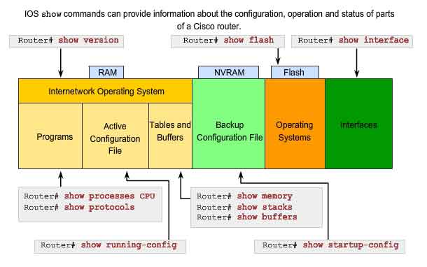
IOS "Examination" Commands
In order to verify and troubleshoot network operation, we must examine the operation of the devices. The basic examination command is the show command. There are many different variations of this command. As you develop more skill with the IOS, you will learn to use and interpret the output of the show commands. Use the show ? command to get a list of available commands in a given context, or mode. The figure indicates how the typical show command can provide information about the configuration, operation, and status of parts of a Cisco router. In this course, we use some of the more basic show commands.
Some of the most commonly used commands are:
show interfaces
Displays statistics for all interfaces on the device. To view the statistics for a specific interface, enter the show interfaces command followed by the specific interface slot/port number. For example:
Router#show interfaces serial 0/1
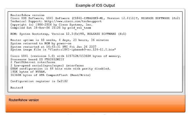
show version
Displays information about the currently loaded software version, along with hardware and device information. Some of the information shown from this command are:
-
Software Version - IOS software version (stored in flash)
- Bootstrap Version - Bootstrap version (stored in Boot ROM)
- System up-time - Time since last reboot
- System restart info - Method of restart (e.g., power cycle, crash)
- Software image name - IOS filename stored in flash
- Router Type and Processor type - Model number and processor type
- Memory type and allocation (Shared/Main) - Main Processor RAM and Shared Packet I/O buffering
- Software Features - Supported protocols / feature sets
- Hardware Interfaces - Interfaces available on router
- Configuration Register - Sets bootup specifications, console speed setting, and related parameters.
The figure shows a sample of typical show version output.
-
show arp - Displays the ARP table of the device.
- show mac-address-table - (switch only) Displays the MAC table of a switch.
- show startup-config - Displays the saved configuration located in NVRAM.
- show running-config - Displays the contents of the currently running configuration file or the configuration for a specific interface, or map class information.
- show ip interfaces - Displays IPv4 statistics for all interfaces on a router. To view the statistics for a specific interface, enter the show ip interfaces command followed by the specific interface slot/port number. Another important format of this command is show ip interface brief. This is useful to get a quick summary of the interfaces and their operational state.
For example:
Router#show ip interface brief
Interface IP-Address OK? Method Status Protocol
FastEthernet0/0 172.16.255.254 YES manual up up
FastEthernet0/1 unassigned YES unset down down
Serial0/0/0 10.10.10.5 YES manual up up
Serial0/0/1 unassigned YES unset down down
The More Prompt
When a command returns more output than can be displayed on a single screen, the --More-- prompt appears at the bottom of the screen. When a --More-- prompt appears, press the Spacebar to view the next portion of output. To display only the next line, press the Enter key. If any other key is pressed, the output is cancelled and you are returned to the prompt.
IOS Configuration Modes
Global Configuration Mode
The primary configuration mode is called global configuration or global config. From global config, CLI configuration changes are made that affect the operation of the device as a whole. We also use the global config mode as a precursor to accessing specific configuration modes. The following CLI command is used to take the device from privileged EXEC mode to the global configuration mode and to allow entry of configuration commands from a terminal:
Router#configure terminal
Once the command is executed, the prompt changes to show that the router is in global configuration mode.
Router(config)#
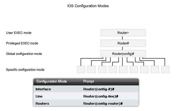
Specific Configuration Modes
From the global config mode, there are many different configuration modes that may be entered. Each of these modes allows the configuration of a particular part or function of the IOS device. The list below shows a few of them:
-
Interface mode - to configure one of the network interfaces (Fa0/0, S0/0/0,..)
- Line mode - to configure one of the lines (physical or virtual) (console, AUX, VTY,..)
- Router mode - to configure the parameters for one of the routing protocols
The figure shows the prompts for some modes. Remember, as configuration changes are made within an interface or process, the changes only affect that interface or process. To exit a specific configuration mode and return to global configuration mode, enter exit at a prompt. To leave configuration mode completely and return to privileged EXEC mode, enter end or use the key sequence Ctrl-Z. Once a change has been made from the global mode, it is good practice to save it to the startup configuration file stored in NVRAM. This prevents changes from being lost due to power failure or a deliberate restart. The command to save the running configuration to startup configuration file is:
Router#copy running-config startup-config
Applying a Basic Configuration Using Cisco IOS
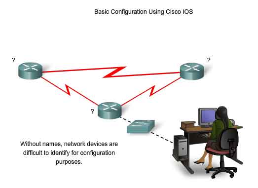
Devices Need Names
The hostname is used in CLI prompts. If the hostname is not explicitly configured, a router uses the factory-assigned default hostname "Router." A switch has a factory-assigned default hostname, "Switch." Imagine if an internetwork had several routers that were all named with the default name "Router." This would create considerable confusion during network configuration and maintenance. When accessing a remote device using Telnet or SSH, it is important to have confirmation that an attachment has been made to the proper device. If all devices were left with their default names, we could not identify that the proper device is connected. By choosing and documenting names wisely, it is easier to remember, discuss, and identify network devices. To name devices in a consistent and useful way requires the establishment of a naming convention that spans the company or, at least, the location. It is a good practice to create the naming convention at the same time as the addressing scheme to allow for continuity within the organization. Some guidelines for naming conventions are that names should:
-
Start with a letter
- Not contain a space
- End with a letter or digit
- Have characters of only letters, digits, and dashes
- Be 63 characters or fewer
The hostnames used in the device IOS preserve capitalization and lower case characters. Therefore, it allows you to capitalize a name as you ordinarily would. This contrasts with most Internet naming schemes, where uppercase and lowercase characters are treated identically. RFC 1178 provides some of the rules that can be used as a reference for device naming. As part of the device configuration, a unique hostname should be configured for each device.
Note: Device host names are only used by administrators when they use the CLI to configure and monitor devices. Unless configured to do so, the devices themselves do not use these names when they discover each other and interoperate.
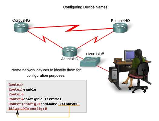
Applying Names - an Example
Let's use an example of three routers connected together in a network spanning three different cities (Atlanta, Phoenix, and Corpus) as shown in the figure. To create a naming convention for routers, take into consideration the location and the purpose of the devices. Ask yourself questions such as these: Will these routers be part of an organization's headquarters? Does each router have a different purpose? For example, is the Atlanta router a primary junction point in the network or is it one junction in a chain? In this example, we will identify each router as a branch headquarters for each city. The names could be AtlantaHQ, PhoenixHQ, and CorpusHQ. Had each router been a junction in a successive chain, the names could be AtlantaJunction1, PhoenixJunction2, and CorpusJunction3. In the network documentation, we would include these names, and the reasons for choosing them, to ensure continuity in our naming convention as devices are added.
Once the naming convention has been identified, the next step is to apply the names to the router using the CLI. This example will walk us through the naming of the Atlanta router.
Configure IOS Hostname
From the privileged EXEC mode, access the global configuration mode by entering the configure terminal command:
Router#configure terminal
After the command is executed, the prompt will change to:
Router(config)#
In the global mode, enter the hostname:
Router(config)#hostname AtlantaHQ
After the command is executed, the prompt will change to:
AtlantaHQ(config)#
Notice that the hostname appears in the prompt. To exit global mode, use the exit command.
Always make sure that your documentation is updated each time a device is added or modified. Identify devices in the documentation by their location, purpose, and address.
Note: To negate the effects of a command, preface the command with the no keyword.
For example, to remove the name of a device, use:
AtlantaHQ(config)# no hostname
Router(config)#
Notice that the no hostname command caused the router to revert to the default hostname of "Router."
RFC 1178, "Choosing a Name for Your Computer,"
http://www.faqs.org/rfcs/rfc1178.html
Limiting Device Access - Configuring Passwords and Using Banners
Physically limiting access to network devices with closets and locked racks is a good practice; however, passwords are the primary defense against unauthorized access to network devices. Every device should have locally configured passwords to limit access. In a later course, we will introduce how to strengthen security by requiring a userID along with a password. For now, we will present basic security precautions using only passwords. As discussed previously, the IOS uses hierarchical modes to help with device security. As part of this security enforcement, the IOS can accept several passwords to allow different access privileges to the device.
The passwords introduced here are:
-
Console password - limits device access using the console connection
- Enable password - limits access to the privileged EXEC mode
- Enable secret password - encrypted, limits access to the privileged EXEC mode
- VTY password - limits device access using Telnet
As good practice, use different authentication passwords for each of these levels of access. Although logging in with multiple and different passwords is inconvenient, it is a necessary precaution to properly protect the network infrastructure from unauthorized access. Additionally, use strong passwords that are not easily guessed. The use of weak or easily guessed passwords continues to be a security issue in many facets of the business world. Consider these key points when choosing passwords:
-
Use passwords that are more than 8 characters in length.
- Use a combination of upper and lowercase and/or numeric sequences in passwords.
- Avoid using the same password for all devices.
- Avoid using common words such as password or administrator, because these are easily guessed.
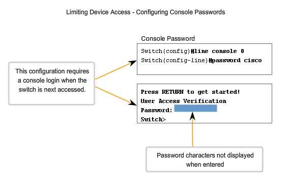
Note: In most of the labs, we will be using simple passwords such as cisco or class. These passwords are considered weak and easily guessable and should be avoided in a production environment. We only use these passwords for convenience in a classroom setting. As shown in the figure, when prompted for a password, the device will not echo the password as it is being entered. In other words, the password characters will not appear when you type. This is done for security purposes - many passwords are gathered by prying eyes.
Console Password
The console port of a Cisco IOS device has special privileges. The console port of network devices must be secured, at a bare minimum, by requiring the user to supply a strong password. This reduces the chance of unauthorized personnel physically plugging a cable into the device and gaining device access. The following commands are used in global configuration mode to set a password for the console line:
Switch(config)#line console 0
Switch(config-line)#password password
Switch(config-line)#login
From global configuration mode, the command line console 0 is used to enter line configuration mode for the console. The zero is used to represent the first (and in most cases only) console interface for a router. The second command, password password specifies a password on a line. The login command configures the router to require authentication upon login. When login is enabled and a password set, there will be a prompt to enter a password. Once these three commands are executed, a password prompt will appear each time a user attempts to gain access to the console port.
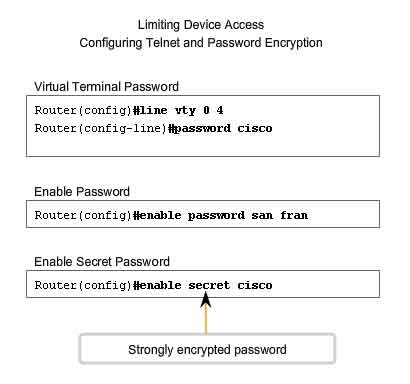
Enable and Enable Secret Passwords
To provide additional security, use the enable password command or the enable secret command. Either of these commands can be used to establish authentication before accessing privileged EXEC (enable) mode. Always use the enable secret command, not the older enable password command, if possible. The enable secret command provides greater security because the password is encrypted. The enable password command can be used only if enable secret has not yet been set. The enable password command would be used if the device uses an older copy of the Cisco IOS software that does not recognize the enable secret command. The following commands are used to set the passwords:
Router(config)#enable password password
Router(config)#enable secret password
Note: If no enable password or enable secret password is set, the IOS prevents privileged EXEC access from a Telnet session. Without an enable password having been set, a Telnet session would appear this way:
Switch>enable
% No password set
Switch>
VTY Password
The vty lines allow access to a router via Telnet. By default, many Cisco devices support five VTY lines that are numbered 0 to 4. A password needs to be set for all available vty lines. The same password can be set for all connections. However, it is often desirable that a unique password be set for one line to provide a fall-back for administrative entry to the device if the other connections are in use. The following commands are used to set a password on vty lines:
Router(config)#line vty 0 4
Router(config-line)#password password
Router(config-line)#login
By default, the IOS includes the login command on the VTY lines. This prevents Telnet access to the device without first requiring authentication. If, by mistake, the no login command is set, which removes the requirement for authentication, unauthorized persons could connect to the line using Telnet. This would be a major security risk.
Encrypting Password Display
Another useful command prevents passwords from showing up as plain text when viewing the configuration files. This is the service password-encryption command. This command causes the encryption of passwords to occur when a password is configured. The service password-encryption command applies weak encryption to all unencrypted passwords. This encryption does not apply to passwords as they are sent over media only in the configuration. The purpose of this command is to keep unauthorized individuals from viewing passwords in the configuration file. If you execute the show running-config or show startup-config command prior to the service password-encryption command being executed, the unencrypted passwords are visible in the configuration output. The service password-encryption can then be executed and the encryption will be applied to the passwords. Once the encryption has been applied, removing the encryption service does not reverse the encryption.
Banner Messages
Although requiring passwords is one way to keep unauthorized personnel out of a network, it is vital to provide a method for declaring that only authorized personnel should attempt to gain entry into the device. To do this, add a banner to the device output. Banners can be an important part of the legal process in the event that someone is prosecuted for breaking into a device. Some legal systems do not allow prosecution, or even the monitoring of users, unless a notification is visible. The exact content or wording of a banner depends on the local laws and corporate policies. Here are some examples of information to include in a banner:
-
"Use of the device is specifically for authorized personnel."
- "Activity may be monitored."
- "Legal action will be pursued for any unauthorized use."
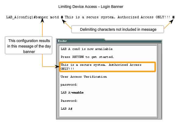
Because banners can be seen by anyone who attempts to log in, the message must be worded very carefully. Any wording that implies that a login is "welcome" or "invited" is not appropriate. If a person disrupts the network after gaining unauthorized entry, proving liability will be difficult if there is the appearance of an invitation. The creation of banners is a simple process; however, banners should be used appropriately. When a banner is utilized it should never welcome someone to the router. It should detail that only authorized personnel are allowed to access the device. Further, the banner can include scheduled system shutdowns and other information that affects all network users. The IOS provides multiple types of banners. One common banner is the message of the day (MOTD). It is often used for legal notification because it is displayed to all connected terminals.
Configure MOTD using the banner motd command from global mode.
As shown in the figure, the banner motd command requires the use of delimiters to identify the content of the banner message. The banner motd command is followed by a space and a delimiting character. Then, one or more lines of text are entered to represent the banner message. A second occurrence of the delimiting character denotes the end of the message. The delimiting character can be any character as long as it does not occur in the message. For this reason, symbols such as the "#" are often used. To configure a MOTD, from global configuration mode enter the banner motd command:
Switch(config)#banner motd # message #
Once the command is executed, the banner will be displayed on all subsequent attempts to access the device until the banner is removed.
Managing Configuration Files
As we have discussed, modifying a running configuration affects the operation of the device immediately. After making changes to a configuration, consider these options for the next step:
-
Make the changed configuration the new startup configuration.
- Return the device to its original configuration.
- Remove all configuration from the device.
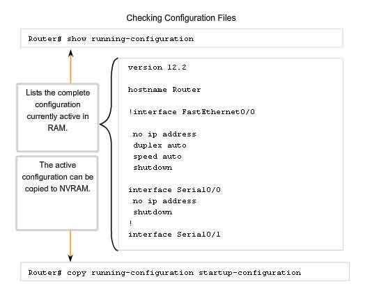
Make the Changed Configuration the New Startup Configuration
Remember, because the running configuration is stored in RAM, it is temporarily active while the Cisco device is running (powered on). If power to the router is lost or if the router is restarted, all configuration changes will be lost unless they have been saved. Saving the running configuration to the startup configuration file in NVRAM preserves the changes as the new startup configuration. Before committing to the changes, use the appropriate show commands to verify the device's operation. As shown in the figure, the show running-config command can be used to see a running configuration file. When the changes are verified to be correct, use the copy running-config startup-config command at the privileged EXEC mode prompt. The following example shows the command:
Switch#copy running-config startup-config
Once executed, the running configuration file replaces the startup configuration file.
Return the Device to Its Original Configuration
If the changes made to the running configuration do not have the desired effect, it may become necessary to restore the device to its previous configuration. Assuming that we have not overwritten the startup configuration with the changes, we can replace the running configuration with the startup configuration. This is best done by restarting the device using the reload command at the privileged EXEC mode prompt. When initiating a reload, the IOS will detect that the running config has changes that were not saved to startup configuration. A prompt will appear to ask whether to save the changes made. To discard the changes, enter n or no. An additional prompt will appear to confirm the reload. To confirm, press the Enter key. Pressing any other key will abort the process. For example:
Router#reload
System configuration has been modified. Save? [yes/no]: n
Proceed with reload? [confirm]
*Apr 13 01:34:15.758: %SYS-5-RELOAD: Reload requested by console. Reload Reason:
Reload Command.
System Bootstrap, Version 12.3(8r)T8, RELEASE SOFTWARE (fc1)
Technical Support: http://www.cisco.com/techsupport
Copyright (c) 2004 by cisco Systems, Inc.
PLD version 0x10
GIO ASIC version 0x127
c1841 processor with 131072 Kbytes of main memory
Main memory is configured to 64 bit mode with parity disabled
Backing Up Configurations Offline
Configuration files should be stored as backup files in the event of a problem. Configuration files can be stored on a Trivial File Transfer Protocol (TFTP) server, a CD, a USB memory stick, or a floppy disk stored in a safe place. A configuration file should also be included in the network documentation.
Backup Configuration on TFTP Server
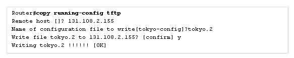
As shown in the figure, one option is to save the running configuration or the startup configuration to a TFTP server. Use either the copy running-config tftp or copy startup-config tftp command and follow these steps:
1. Enter the copy running-config tftp command.
2. Enter the IP address of the host where the configuration file will be stored.
3. Enter the name to assign to the configuration file.
4. Answer yes to confirm each choice.
Removing All Configurations
If undesired changes are saved to the startup configuration, it may be necessary to clear all the configurations. This requires erasing the startup configuration and restarting the device.
The startup configuration is removed by using the erase startup-config command.
To erase the startup configuration file use erase NVRAM:startup-config or erase startup-config at the privileged EXEC mode prompt:
Router#erase startup-config
Once the command is issued, the router will prompt you for confirmation:
Erasing the nvram filesystem will remove all configuration files! Continue? [confirm]
Confirm is the default response. To confirm and erase the startup configuration file, press the Enter key. Pressing any other key will abort the process. Caution: Exercise care when using the erase command. This command can be used to erase any file in the device. Improper use of the command can erase the IOS itself or another critical file. After removing the startup configuration from NVRAM, reload the device to remove the current running configuration file from RAM. The device will then load the default startup configuration that was originally shipped with the device into the running configuration.
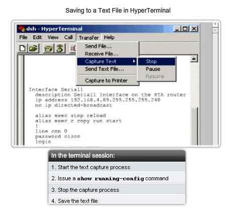
Backup Configurations with Text Capture (HyperTerminal)
Configuration files can be saved/archived to a text document. This sequence of steps ensures that a working copy of the configuration files is available for editing or reuse later. When using HyperTerminal, follow these steps:
1. On the Transfer menu, click Capture Text.
2. Choose the location.
3. Click Start to begin capturing text.
4. Once capture has been started, execute the show running-config or show startup-config command at the privileged EXEC prompt. Text displayed in the terminal window will be placed into the chosen file.
5. View the output to verify that it was not corrupted.
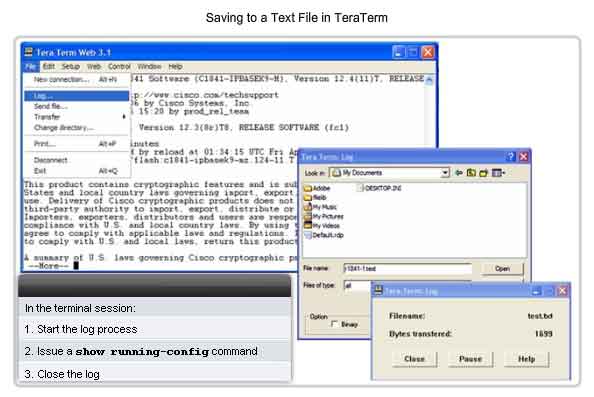
Backup Configurations with Text Capture (TeraTerm)
Configuration files can be saved/archived to a text document using TeraTerm.
As shown in the figure, the steps are:
1. On the File menu, click Log.
2. Choose the location. TeraTerm will begin capturing text.
3. Once capture has been started, execute the show running-config or show startup-config command at the privileged EXEC prompt. Text displayed in the terminal window will be placed into the chosen file.
4. When the capture is complete, select Close in the TeraTerm: Log window.
5. View the output to verify that it was not corrupted.
Restoring Text Configurations
A configuration file can be copied from storage to a device. When copied into the terminal, the IOS executes each line of the configuration text as a command. This means that the file will require editing to ensure that encrypted passwords are in plain text and that non-command text such as "--More--" and IOS messages are removed. This process is discussed in the lab. Further, at the CLI, the device must be set at the global configuration mode to receive the commands from the text file being copied. When using HyperTerminal, the steps are:
1. Locate the file to be copied into the device and open the text document.
2. Copy all of the text.
3. On the Edit menu, click paste to host.
When using TeraTerm, the steps are:
1. On the File menu, click Send file.
2. Locate the file to be copied into the device and click Open.
3. TeraTerm will paste the file into the device.
The text in the file will be applied as commands in the CLI and become the running configuration on the device. This is a convenient method for manually configuring a router.
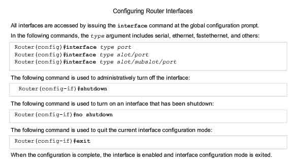
Configuring Interfaces
Throughout this chapter, we have discussed commands that are generic to IOS devices. Some configurations are specific to a type of device. One such configuration is the configuration of interfaces on a router. Most intermediary network devices have an IP address for the purpose of device management. Some devices, such as switches and wireless access points, can operate without having an IP address. Because the purpose of a router is to interconnect different networks, each interface on a router has its own unique IPv4 address. The address assigned to each interface exists in a separate network devoted to the interconnection of routers. There are many parameters that can be configured on router interfaces. We will discuss the most basic interface commands, which are summarized in the figure.
Configuring Router Ethernet Interfaces
Router Ethernet interfaces are used as the gateways for the end devices on the LANs directly connected to the router. Each Ethernet interface must have an IP address and subnet mask to route IP packets. To configure an Ethernet interface follow these steps:
1. Enter global configuration mode.
2. Enter interface configuration mode.
3. Specify the interface address and subnet mask.
4. Enable the interface.
As shown in the figure, configure the Ethernet IP address using the following commands:
Router(config)#interface FastEthernet 0/0
Router(config-if)#ip address ip_address netmask
Router(config-if)#no shutdown
Enabling the Interface
By default, interfaces are disabled. To enable an interface, enter the no shutdown command from the interface configuration mode. If an interface needs to be disabled for maintenance or troubleshooting, use the shutdown command.
Configuring Router Serial Interfaces
Serial interfaces are used to connect WANs to routers at a remote site or ISP.
To configure a serial interface follow these steps:
1. Enter global configuration mode.
2. Enter interface mode.
3. Specify the interface address and subnet mask.
4. Set the clock rate if a DCE cable is connected. Skip this step if a DTE cable is connected.
5. Turn on the interface.
Each connected serial interface must have an IP address and subnet mask to route IP packets. Configure the IP address with the following commands:
Router(config)#interface Serial 0/0/0
Router(config-if)#ip address ip_address netmask
Serial interfaces require a clock signal to control the timing of the communications. In most environments, a DCE device such as a CSU/DSU will provide the clock. By default, Cisco routers are DTE devices, but they can be configured as DCE devices. On serial links that are directly interconnected, as in our lab environment, one side must operate as DCE to provide a clocking signal. The clock is enabled and the speed is specified with the clock rate command. Some bit rates might not be available on certain serial interfaces. This depends on the capacity of each interface. In the lab, if a clock rate needs to be set on an interface identified as DCE, use the 56000 clock rate. As shown in the figure, the commands that are used to set a clock rate and enable a serial interface are:
Router(config)#interface Serial 0/0/0
Router(config-if)#clock rate 56000
Router(config-if)#no shutdown
Once configuration changes are made to the router, remember to use the show commands to verify the accuracy of the changes, and then save the changed configuration as the startup configuration.
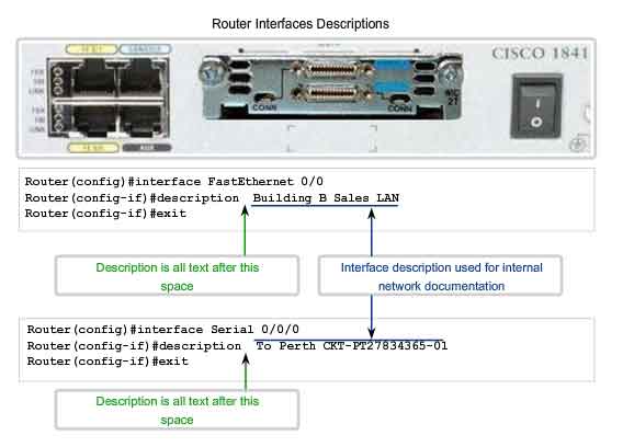
As the hostname helps to identify the device on a network, an interface description indicates the purpose of the interface. A description of what an interface does or where it is connected should be part of the configuration of each interface. This description can be useful for troubleshooting. The interface description will appear in the output of these commands: show startup-config, show running-config, and show interfaces. For example, this description provides valuable information about the purpose of the interface:
This interface is the gateway for the administration LAN.
A description can assist in determining the devices or locations connected to the interface. Here is another example:
Interface F0/0 is connected to the main switch in the administration building.
When support personnel can easily identify the purpose of an interface or connected device, they can more easily understand the scope of a problem, and this can lead to reaching a resolution sooner. Circuit and contact information can also be embedded in the interface description. The following description for a serial interface provides the information the network administrator may need before deciding to test a WAN circuit. This description indicates where the circuit terminates, the circuit ID, and the phone number of the company supplying the circuit:
FR to GAD1 circuit ID:AA.HCGN.556460 DLCI 511 - support# 555.1212
To create a description, use the command description. This example shows the commands used to create a description for a FastEthernet interface:
HQ-switch1#configure terminal
HQ-switch1(config)#interface fa0/0
HQ-switch1(config-if)#description Connects to main switch in Building A
Once the description is applied to the interface, use the show interfaces command to verify the description is correct.
Configuring a Switch Interface
A LAN switch is an intermediary device that interconnects segments within a network. Therefore, the physical interfaces on the switch do not have IP addresses. Unlike a router where the physical interfaces are connected to different networks, a physical interface on a switch connects devices within a network. Switch interfaces are also enabled by default. As shown in the Switch 1 figure, we can assign descriptions but do not have to enable the interface. In order to be able to manage a switch, we assign addresses to the device to it. With an IP address assigned to the switch, it acts like a host device. Once the address is assigned, we access the switch with telnet, ssh or web services. The address for a switch is assigned to a virtual interface represented as a Virtual LAN interface (VLAN). In most cases, this is the interface VLAN 1. In the Switch 2 figure, we assign an IP address to the VLAN 1 interface. Like the physical interfaces of a router, we also must enable this interface with the no shutdown command. Like any other host, the switch needs a gateway address defined to communicate outside of the local network. As shown in the Switch 2 figure, we assign this gateway with the ip default-gateway command.
Verifying Connectivity
Test the Stack
The Ping Command
Using the ping command is an effective way to test connectivity. The test is often referred to as testing the protocol stack, because the ping command moves from Layer 3 of the OSI model to Layer 2 and then Layer 1. Ping uses the ICMP protocol to check for connectivity.
Using ping in a Testing Sequence
In this section, we will use the router IOS ping command in a planned sequence of steps to establish valid connections, starting with the individual device and then extending to the LAN and, finally, to remote networks. By using the ping command in this ordered sequence, problems can be isolated. The ping command will not always pinpoint the nature of the problem, but it can help to identify the source of the problem, an important first step in troubleshooting a network failure. The ping command provides a method for checking the protocol stack and IPv4 address configuration on a host. There are additional tools that can provide more information than ping, such as Telnet or Trace, which will be discussed in more detail later.
IOS Ping Indicators
A ping from the IOS will yield to one of several indications for each ICMP echo that was sent. The most common indicators are:
-
! - indicates receipt of an ICMP echo reply
- . - indicates a timed out while waiting for a reply
- U - an ICMP unreachable message was received
The "!" (exclamation mark) indicates that the ping completed successfully and verifies Layer 3 connectivity. The "." (period) can indicate problems in the communication. It may indicate connectivity problem occurred somewhere along the path. It also may indicate a router along the path did not have a route to the destination and did not send an ICMP destination unreachable message. It also may indicate that ping was blocked by device security. The "U" indicates that a router along the path did not have a route to the destination address and responded with an ICMP unreachable message.
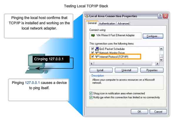
Testing the Loopback
As a first step in the testing sequence, the ping command is used to verify the internal IP configuration on the local host. Recall that this test is accomplished by using the ping command on a reserved address called the loopback (127.0.0.1). This verifies the proper operation of the protocol stack from the Network layer to the Physical layer - and back - without actually putting a signal on the media.
Ping commands are entered into a command line.
Enter the ping loopback command with this syntax:
C:>ping 127.0.0.1
The reply from this command would look something like this:
Reply from 127.0.0.1: bytes=32 time<1ms TTL=128
Reply from 127.0.0.1: bytes=32 time<1ms TTL=128
Reply from 127.0.0.1: bytes=32 time<1ms TTL=128
Reply from 127.0.0.1: bytes=32 time<1ms TTL=128
Ping statistics for 127.0.0.1:
Packets: Sent = 4, Received = 4, Lost = 0 (0% loss),
Approximate round trip times in milli-seconds:
Minimum = 0ms, Maximum = 0ms, Average = 0ms
The result indicates that four test packets were sent - each 32 bytes in size - and were returned from host 127.0.0.1 in a time of less than 1 ms. TTL stands for Time to Live and defines the number of hops that the ping packet has remaining before it will be dropped.
Testing the Interface Assignment
In the same way that you use commands and utilities to verify a host configuration, you need to learn commands to verify the interfaces of intermediary devices. The IOS provides commands to verify the operation of router and switch interfaces.
Verifying the Router Interfaces
One of the most used commands is the show ip interface brief command. This provides a more abbreviated output than the show ip interface command. This provides a summary of the key information for all the interfaces. Looking at the Router 1 figure, we can see that this output shows all interfaces attached on the router, the IP address, if any, assigned to each interface, and the operational status of the interface. Looking at the line for the FastEthernet 0/0 interface, we see that the IP address is 192.168.254.254. Looking at the last two columns, we can see the Layer 1 and Layer 2 status of the interface. The up in the Status column shows that this interface is operational at Layer 1. The up in the Protocol column indicates that the Layer 2 protocol is operational. In the same figure, notice that the Serial 0/0/1 interface has not been enabled. This is indicated by administratively down in the Status column. This interface can be enabled with the no shutdown command.
Testing Router Connectivity
As with an end device, we can verify the Layer 3 connectivity with the ping and traceroute commands. In the Router 1 figure, you can see sample outputs from a ping to a host in the local LAN and a trace to a remote host across the WAN.
Verifying the Switch Interfaces
Examining the Switch 1 figure, you can see the use of the show ip interface command to verify the condition of the switch interfaces. As you learned earlier, the IP address for the switch is applied to a VLAN interface. In this case, the Vlan1 interface is assigned an IP address 192.168.254.250. We can also see that this interface has been enabled and is operational. Examining the FastEthernet0/1 interface, you can see that this interface is down. This indicates that no device is connected to the interface or the network interface of the devices that is connected is not operational. In contrast, the outputs for the FastEthernet0/2 and FastEthernet0/3 interfaces are operational. This is indicated by both the Status and Protocol being shown as up.
Testing Switch Connectivity
Like other hosts, the switch can test its Layer 3 connectivity with the ping and traceroute commands. The Switch1 figure also shows a ping to the local host and a trace to a remote host. Two important things to keep in mind are that an IP address is not required for a switch to perform its job of frame forwarding and that the switch requires a gateway to communicate outside its local network.
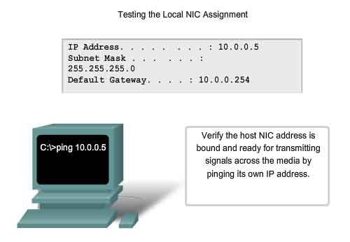
The next step in the testing sequence is to verify that the NIC address is bound to the IPv4 address and that the NIC is ready to transmit signals across the media. In this example, also shown in the figure, assume that the IPv4 address assigned to a NIC is 10.0.0.5. To verify the IPv4 address, use the following steps:
At the command line, enter the following:
C:>ping 10.0.0.5
A successful reply would resemble:
Reply from 10.0.0.5: bytes=32 time<1ms TTL=128
Reply from 10.0.0.5: bytes=32 time<1ms TTL=128
Reply from 10.0.0.5: bytes=32 time<1ms TTL=128
Reply from 10.0.0.5: bytes=32 time<1ms TTL=128
Ping statistics for 10.0.0.5:
Packets: Sent = 4, Received = 4, Lost = 0 (0% loss),
Approximate round trip times in milli-seconds:
Minimum = 0ms, Maximum = 0ms, Average = 0ms
This test verifies that the NIC driver and most of the NIC hardware are working properly. It also verifies that the IP address is properly bound to the NIC, without actually putting a signal on the media. If this test fails, it is likely that there are issues with the NIC hardware and software driver that may require reinstallation of either or both. This procedure is dependent on the type of host and its operating system.
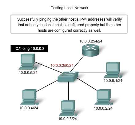
Testing Local Network
The next test in the sequence is to test hosts on the local LAN. Successfully pinging remote hosts verifies that both the local host (the router in this case) and the remote host are configured correctly. This test is conducted by pinging each host one by one on the LAN. If a host responds with Destination Unreachable, note which address was not successful and continue to ping the other hosts on the LAN. Another failure message is Request Timed Out. This indicates that no response was made to the ping attempt in the default time period indicating that network latency may be an issue.
Extended Ping
To examine this the IOS offers an "extended" mode of the ping command. This mode is entered by typing ping in privileged EXEC mode, at the CLI prompt without a destination IP address. A series of prompts are then presented as shown in this example. Pressing Enter accepts the indicated default values.
Router#ping
Protocol [ip]:
Target IP address:10.0.0.1
Repeat count [5]:
Datagram size [100]:
Timeout in seconds [2]:5
Extended commands [n]: n
Entering a longer timeout period than the default allows for possible latency issues to be detected. If the ping test is successful with a longer value, a connection exists between the hosts, but latency may be an issue on the network. Note that entering "y" to the "Extended commands" prompt provides more options that are useful in troubleshooting - you will explore these options in the Lab and Packet Tracer activities.
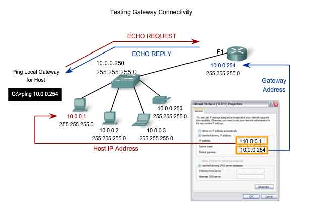
Testing Gateway and Remote Connectivity
The next step in the testing sequence is to use the ping command to verify that a local host can connect with a gateway address. This is extremely important because the gateway is the host's entry and exit to the wider network. If the ping command returns a successful response, connectivity to the gateway is verified. To begin, choose a station as the source device. In this case, we chose 10.0.0.1, as shown in the figure. Use the ping command to reach the gateway address, in this case, 10.0.0.254.
c:>ping 10.0.0.254
The gateway IPv4 address should be readily available in the network documentation, but if it is not available, use the ipconfig command to discover the gateway IP address.
Testing Route Next Hop
In a router, use the IOS to test the next hop of the individual routes. As you learned, each route has the next hop listed in the routing table. To determine the next hop, examine the routing table from the output of the show ip route command. Frames carrying packets that are directed to the destination network listed in the routing table are sent to the device that represents the next hop. If the next hop is not accessible, the packet will be dropped. To test the next hop, determine the appropriate route to the destination and try to ping the default gateway or appropriate next hop for that route in the routing table. A failed ping indicates that there might be a configuration or hardware problem. However, the ping may also be prohibited by security in the device. If the gateway test fails, back up one step in the sequence and test another host in the local LAN to verify that the problem is not the source host. Then verify the gateway address with the network administrator to ensure that the proper address is being tested. If all devices are configured properly, check the physical cabling to ensure that it is secure and properly connected. Keep an accurate record of what attempts have been made to verify connectivity. This will assist in solving this problem and, perhaps, future problems.
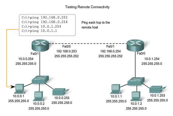
Testing Remote Hosts
Once verification of the local LAN and gateway is complete, testing can proceed to remote devices, which is the next step in the testing sequence. The figure depicts a sample network topology. There are 3 hosts within a LAN, a router (acting as the gateway) that is connected to another router (acting as the gateway for a remote LAN), and 3 remote hosts. The verification tests should begin within the local network and progress outward to the remote devices. Begin by testing the outside interface of a router that is directly connected to a remote network. In this case, the ping command is testing the connection to 192.168.0.253, the outside interface of the local network gateway router. If the ping command is successful, connectivity to the outside interface is verified. Next, ping the outside IP address of the remote router, in this case, 192.168.0.254. If successful, connectivity to the remote router is verified. If there is a failure, try to isolate the problem. Retest until there is a valid connection to a device and double-check all addresses. The ping command will not always help with identifying the underlying cause to a problem, but it can isolate problems and give direction to the troubleshooting process. Document every test, the devices involved, and the results.
Check for Router Remote Connectivity
A router forms a connection between networks by forwarding packets between them. To forward packets between any two networks, the router must be able to communicate with both the source and the destination networks. The router will need routes to both networks in its routing table. To test the communication to the remote network, you can ping a known host on this remote network. If you cannot successfully ping the host on the remote network from a router, you should first check the routing table for an appropriate route to reach the remote network. It may be that the router uses the default route to reach a destination. If there is no route to reach this network, you will need to identify why the route does not exist. As always, you also must rule out that the ping is not administratively prohibited.
Tracing and Interpreting Trace Results
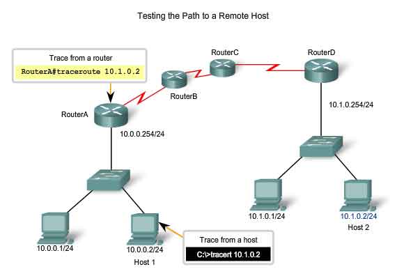
The next step in the testing sequence is to perform a trace. A trace returns a list of hops as a packet is routed through a network. The form of the command depends on where the command is issued. When performing the trace from a Windows computer, use tracert. When performing the trace from a router CLI, use traceroute.
Ping and Trace
Ping and trace can be used together to diagnose a problem. Let's assume that a successful connection has been established between Host 1 and Router A, as shown in the figure. Next, let's assume that Host 1 pings Host 2 using this command.
C:>ping 10.1.0.2
The ping command returns this result:
Pinging 10.1.0.2 with 32 bytes of data:
Request timed out.
Request timed out.
Request timed out.
Request timed out.
Ping statistics for 10.1.0.2:
Packets: Sent = 4, Received = 0, Lost = 4 (100% loss)
The ping test failed.
This is a test of communication beyond the local network to a remote device. Because the local gateway responded but the host beyond did not, the problem appears to be somewhere beyond the local network. A next step is to isolate the problem to a particular network beyond the local network. The trace commands can show the path of the last successful communication.
Trace to a Remote Host
Like ping commands, trace commands are entered in the command line and take an IP address as the argument. Assuming that the command will be issued from a Windows computer, we use the tracert form:
C:>tracert 10.1.0.2
Tracing route to 10.1.0.2 over a maximum of 30 hops
1 2 ms 2 ms 2 ms 10.0.0.254
2 * * * Request timed out.
3 * * * Request timed out.
4 ^C
The only successful response was from the gateway on Router A. Trace requests to the next hop timed out, meaning that the next hop did not respond. The trace results indicate that the failure is therefore in the internetwork beyond the LAN.
Testing Sequence - Putting it all Together
As a review, let's walk through the testing sequence in another scenario.
Test 1: Local Loopback - Successful
C:>ping 127.0.0.1
Pinging 127.0.0.1 with 32 bytes of data:
Reply from 127.0.0.1: bytes=32 time<1ms TTL=128
Reply from 127.0.0.1: bytes=32 time<1ms TTL=128
Reply from 127.0.0.1: bytes=32 time<1ms TTL=128
Reply from 127.0.0.1: bytes=32 time<1ms TTL=128
Ping statistics for 127.0.0.1:
Packets: Sent = 4, Received = 4, Lost = 0 (0% loss),
Approximate round trip times in milli-seconds:
Minimum = 0ms, Maximum = 0ms, Average = 0ms
Host 1has the IP stack properly configured.
Test 2: Local NIC - Successful
C:>ping 192.168.23.3
Pinging 192.168.23.3 with 32 bytes of data:
Reply from 192.168.23.3: bytes=32 time<1ms TTL=128
Reply from 192.168.23.3: bytes=32 time<1ms TTL=128
Reply from 192.168.23.3: bytes=32 time<1ms TTL=128
Reply from 192.168.23.3: bytes=32 time<1ms TTL=128
Ping statistics for 192.168.23.3:
Packets: Sent = 4, Received = 4, Lost = 0 (0% loss),Approximate round trip times in milli-seconds:
Minimum = 0ms, Maximum = 0ms, Average = 0ms
The IP address is properly assigned to the NIC and the electronics in the NIC respond to the IP address.
Test 3: Ping Local Gateway - Successful
C:>ping 192.168.23.254
Pinging 192.168.23.254 with 32 bytes of data:
Reply from 192.168.23.254: bytes=32 time<1ms TTL=128
Reply from 192.168.23.254: bytes=32 time<1ms TTL=128
Reply from 192.168.23.254: bytes=32 time<1ms TTL=128
Reply from 192.168.23.254: bytes=32 time<1ms TTL=128
Ping statistics for 192.168.23.254:
Packets: Sent = 4, Received = 4, Lost = 0 (0% loss),
Approximate round trip times in milli-seconds:
Minimum = 0ms, Maximum = 0ms, Average = 0ms
The default gateway is operational. This also verifies the operation of the local network.
Test 4: Ping Remote Host - Failure
C:>ping 192.168.11.1
Pinging 192.168.11.1 with 32 bytes of data:
Request timed out.
Request timed out.
Request timed out.
Request timed out.
Ping statistics for 192.168.11.1:
Packets: Sent = 4, Received = 0, Lost = 4 (100% loss)
This is a test of the communication beyond the local network. Because the gateway responded but the host beyond did not, the problem appears to be somewhere beyond the local network.
Test 5: Traceroute to Remote Host - Failure at First Hop
C:>tracert 192.168.11.1
Tracing route to 192.168.11.1 over a maximum of 30 hops
1 * * * Request timed out.
2 * * * Request timed out.
3 ^C
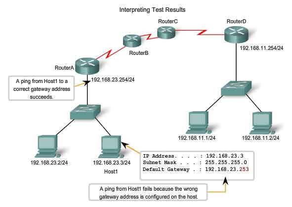
There appear to be conflicting results. The default gateway responds, indicating that there is communication between Host1 and the gateway. On the other hand, the gateway does not appear to be responding to traceroute. One explanation is that the local host is not configured properly to use 192.168.23.254 as the default gateway. To confirm this, we examine the configuration of Host1.
Test 6: Examine Host Configuration for Proper Local Gateway - Incorrect
C:>ipconfig
Windows IP Configuration
Ethernet adapter Local Area Connection:
IP Address. . . . . . . . . . . . : 192.168.23. 3
Subnet Mask . . . . . . . . . . : 255.255.255.0
Default Gateway . . . . . . . : 192.168.23.253
From the output of the ipconfig command, it can be determined that the gateway is not properly configured on the host. This explains the false indication that the problem was in the internetwork beyond the local network. Even though the address 192.168.23.254 responded, this was not the address configured in Host1 as the gateway. Unable to build a frame, Host1 drops the packet. In this case, there is no response indicated from the trace to the remote host.
Monitoring and Documenting of Networks
Basic Network Baselines
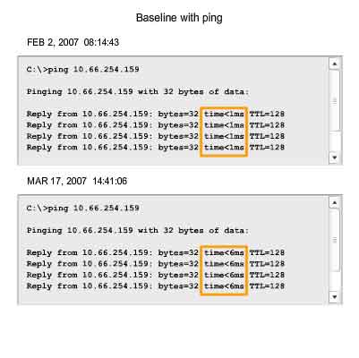
One of the most effective tools for monitoring and troubleshooting network performance is to establish a network baseline. A baseline is a process for studying the network at regular intervals to ensure that the network is working as designed. It is more than a single report detailing the health of the network at a certain point in time. Creating an effective network performance baseline is accomplished over a period of time. Measuring performance at varying times and loads will assist in creating a better picture of overall network performance. The output derived from network commands can contribute data to the network baseline. The figure shows the information to record. One method for starting a baseline is to copy and paste the results from an executed ping, trace, or other relevant command into a text file. These text files can be time stamped with the date and saved into an archive for later retrieval. An effective use of the stored information is to compare the results over time. Among items to consider are error messages and the response times from host to host. If there is a considerable increase in response times, there may be a latency issue to address. The importance of creating documentation cannot be emphasized enough. Verification of host-to-host connectivity, latency issues, and resolutions of identified problems can assist a network administrator in keeping a network running as efficiently as possible. Corporate networks should have extensive baselines; more extensive than we can describe in this course. Professional-grade software tools are available for storing and maintaining baseline information. In this course, we will cover some basic techniques and discuss the purpose of baselines.
Host Capture
One common method for capturing baseline information is to copy the output from the command line window and paste it into a text file. To capture the results of the ping command, begin by executing a command in the command line similar to this one. Substitute a valid IP address on your network.
C:>ping 10.66.254.159
The reply will appear below the command.
With the output still in the command window, follow these steps:
1. Right-click the command prompt window, then click Select All.
2. Press Ctrl-C to copy the output.
3. Open a text editor.
4. Press Ctrl-V to paste the text.
5. Save the text file with the date and time as part of the name.
Run the same test over a period of days and save the data each time. An examination of the files will begin to reveal patterns in network performance and provide the baseline for future troubleshooting. When selecting text from the command window, use the Select All command to copy all the text in the window. Use the Mark command to select a portion of the text.
IOS Capture
Capturing ping command output can also be completed from the IOS prompt. The following steps describe how to capture the output and save to a text file.
When using HyperTerminal for access, the steps are:
1. On the Transfer menu, click Capture Text.
2. Choose Browse to locate or type the name of the saving the file.
3. Click Start to begin capturing text
4. Execute the ping command in the user EXEC mode or at the privileged EXEC prompt. The router will place the text displayed on the terminal in the location chosen.
5. View the output to verify that it was not corrupted.
6. On the Transfer menu, click Capture Text, and then click Stop Capture.
Data generated using either the computer prompt or the router prompt can contribute to the baseline.
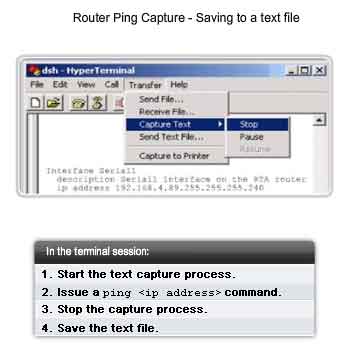
Capturing and Interpreting Trace Information
As previously discussed, trace can be used to trace the steps, or hops, between hosts. If the request reaches the intended destination, the output shows every router that the packet traverses. This output can be captured and used in the same way that ping output is used. Sometimes the security settings at the destination network will prevent the trace from reaching the final destination. However, we can still capture a baseline of the hops along the path. Recall that the form for using trace from a Windows host is tracert.
To trace the route from your computer to cisco.com, enter this command in a command line:
C:>tracert www.cisco.com
The steps for saving the trace output are identical to the steps for saving ping output: Select the text from the command window and paste it into a text file. The data from a trace can be added to the data from the ping commands to provide a combined picture of network performance. For example, if the speed of a ping command decreases over time, compare the trace output for the same time period. Examining the response times on a hop-by-hop comparison may reveal a particular point of longer response time. This delay may be due to congestion at that hop creating a bottleneck in the network. Another case might show that the hop pathway to the destination may vary over time as the routers select different best paths for the trace packets. These variations may show patterns that could be useful in scheduling large transfers between sites.
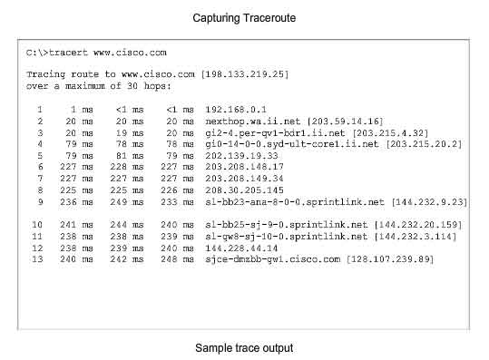
Router Capture
Capturing the traceroute output can also be done from the router prompt. The following steps show how to capture the output and save it to a file. Recall that the form of trace for the router CLI is traceroute.
When using HyperTerminal, the steps used are:
1. On the Transfer menu, click Capture Text.
2. Choose a use Browse to locate or type the name of the saving the file.
3. Click Start to begin capturing text
4. Execute the traceroute command in the user EXEC mode or at the privileged EXEC prompt. The router will place the text displayed on the terminal in the location chosen.
5. View the output to verify that it was not corrupted.
6. On the Transfer menu, click Capture Text, and then click Stop Capture.
Store the text files generated by these tests in a safe location, along with the rest of the network documentation.
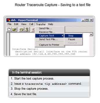
Learning About the Nodes on the Network
If an appropriate addressing scheme exists, identifying IPv4 addresses for devices in a network should be a simple task. Identifying the physical (MAC) addresses, however, can be a daunting task. You would need access to all of the devices and sufficient time to view the information, one host at a time. Because this is not a practical option in many cases, there is an alternate means of MAC address identification using the arp command. The arp command provides for the mapping of physical addresses to known IPv4 addresses. A common method for executing the arp command is to execute it from the command prompt. This method involves sending out an ARP request. The device that needs the information sends out a broadcast ARP request to the network, and only the local device that matches the IP address of the request sends back an ARP reply containing its IP-MAC pair. To execute an arp command, at the command prompt of a host, enter:
C:host1>arp -a
As shown in the figure the arp command lists all devices currently in the ARP cache, which includes the IPv4 address, physical address, and the type of addressing (static/dynamic), for each device. The router cache can be cleared by using the arp -d command, in the event the network administrator wants to repopulate the cache with updated information. Note: The ARP cache is only populated with information from devices that have been recently accessed. To ensure that the ARP cache is populated, ping a device so that it will have an entry in the ARP table.
Ping Sweep
Another method for collecting MAC addresses is to employ a ping sweep across a range of IP addresses. A ping sweep is a scanning method that can be executed at the command line or by using network administration tools. These tools provide a way to specify a range of hosts to ping with one command. Using the ping sweep, network data can be generated in two ways. First, many of the ping sweep tools construct a table of responding hosts. These tables often list the hosts by IP address and MAC address. This provides a map of active hosts at the time of the sweep. As each ping is attempted, an ARP request is made to get the IP address in the ARP cache. This activates each host with recent access and ensures that the ARP table is current. The arp command can return the table of MAC addresses, as discussed above, but now there is reasonable confidence that the ARP table is up-to-date.
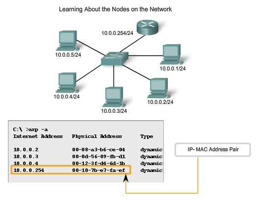
Switch Connections
One additional tool that can be helpful is a mapping of how hosts are connected to a switch. This mapping can be obtained by issuing the show mac-address-table command. Using a command line from a switch, enter the show command with the mac-address-table argument:
Sw1-2950#show mac-address-table
This table in the figure lists the MAC address of the hosts that are connected to this switch. Like other output in the command window, this information can be copied and pasted into a file. Data can also be pasted into a spreadsheet for easier manipulation later. An analysis of this table also reveals that the Fa0/23 interface is either a shared segment or is connected to another switch. Several MAC addresses are representing multiple nodes. This is an indication that a port is connected to another intermediary device such as a hub, wireless access point, or another switch. Additional commands and tools for data gathering presented in later courses.
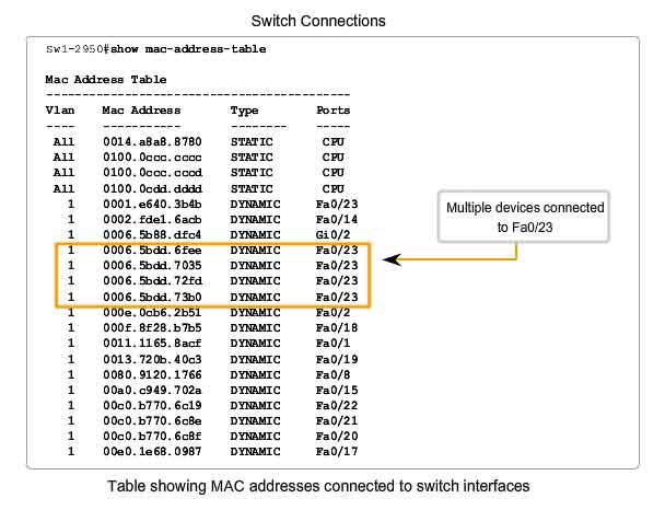
Documenting Network Performance
Use 100 successive pings to the same remote host. Paste these entries into an Excel spreadsheet and create a chart showing the mean, median, mode, and the number and percentage of dropped packets. Hint: Dropped packets have a consistently large value assigned to them. Conduct this test for 3 samples spread out over a 24-hour period and repeated every day for 5 days at approximately the same time. To get a better picture of network performance, try increasing the packet size by 100 bytes at a time for 20 pings. Plot the average values for each of the 20 pings to see the effect of the increase in packet size. Also, note any time there is a large change in throughput.
Summary of IOS features and commands
User EXEC Mode
-
enable - Enter Privileged EXEC mode
Privileged EXEC Mode
-
copy running-config startup-config - Copy the active configuration to NVRAM.
- copy startup-config running-config - Copy the configuration in NVRAM to RAM.
- erase startup-configuration - Erase the configuration located in NVRAM.
- ping ip_address - Ping to that address.
- traceroute ip_address - Trace each hop to that address.
- show interfaces - Display statistics for all interfaces on a device.
- show clock - Show the time set in the router.
- show version - Display currently loaded IOS version, hardware, and device information.
- show arp - Display the ARP table of the device.
- show startup-config - Display the saved configuration located in NVRAM.
- show running-config - Display the contents of the currently running configuration file.
- show ip interface - Display IP statistics for interface(s) on a router.
- configure terminal - Enter terminal configuration mode.
Terminal Configuration Mode
-
hostname hostname - Assign a host name to device.
- enable password password - Set an unencrypted enable password.
- enable secret password - Set a strongly encrypted enable password.
- service password-encryption - Encrypt display of all passwords except secret.
- banner motd# message # - Sets a message-of-the-day banner.
- line console 0 - Enter console line configuration mode.
- line vty 0 4 - Enter virtual terminal (Telnet) line configuration mode.
- interface Interface_name - Enter interface configuration mode.
Line Configuration Mode
-
login - Enable password checking at login.
- password password - Set line password.
Interface Configuration Mode
-
ip address ip_address netmask - Set interface IP address and subnet mask.
- description description - Set interface description.
- clock rate value - Set clock rate for DCE device.
- no shutdown - Set interface to up.
- shutdown - Administratively set interface to down.